Posted on: Jan. 14th, 2021, | By Project Manager Mandy
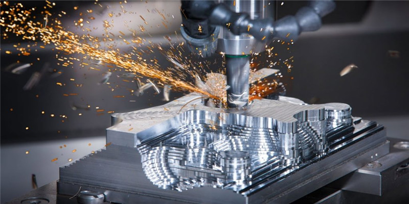
When we plan to order CNC prototypes, the first consideration will be the cost. What can we do to reduce the cost of CNC machining services? I think this article is the topic that designers are most interested in because we can improve production efficiency and reduce costs by following 3 tips.
CNC Split Machining Complex Parts
If the CNC prototype needs to be strong enough for mechanical testing, then machining in one piece is preferred. If your parts are used for design verification or appearance verification, then from the perspective of cost, we would suggest that you consider CNC Split Machining Complex Parts.
Especially for parts with complex structures, they cannot be processed in the same plane. With the CNC Split Machining solution, the parts can be divided into several pieces of different sizes for processing, omitting the 5-axis auxiliary processing or making jigs for positioning and clamping multiple times. These omitting processes are all in saving processing costs. Adopting the CNC Split Machining solution can effectively optimize the process and reduce the processing time.
Optimization cost:
Plastic parts with complex structures, especially shell parts, have large sizes and multi-dimensional structures. The CNC Split Machining solution processing can be adopted. The parts can be divided into several pieces for separate processing and then gluing together. Maybe you’re worried that the glue won’t stick. Rest assured that Wayken has extensive experience in this area and uses special gluing schemes to strengthen parts.
Complex metal parts can also be disassembled, especially those with complex internal structures and internal threads. They can be welded or screw together, so they will be cheaper.
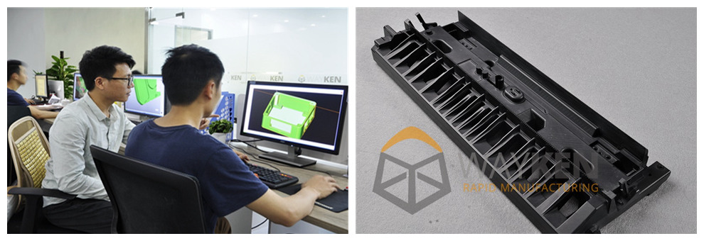
Case Study 1
The following is an example of a CNC Split Machining solution.
Process: CNC Split Machining then gluing
Material: ABS
Post-processing: Paint
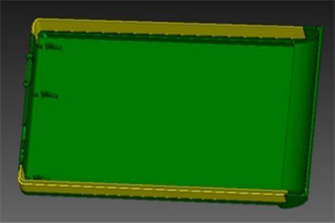
Schematic diagram of CNC Split: Split into 3 pieces, yellow surface, and green surface.
Customer comment: Thank you very much for your proposal, which has saved our budget. Moreover, the painting effect of this part is very good, and there is no gluing mark. Our team is very satisfied with this project.
Internal Fillets
If you look closely during the manufacturing process, all the cutting tools, regardless of their size, are cylindrical and have a certain diameter. This means that the inner angle of the CNC machined part cannot be a radius. What if the corners of our parts must be no radius to ensure assembly? Of course, it is also allowed, plastic parts we usually by hand to clear the corner to get no radius, metal parts can be through the EDM processing to get no radius.
However, these two steps are increasing the cost, so it is suggested that the internal corner radius of the parts can be increased if conditions permit, so as to apply a larger tool for processing and shorten the processing time.
Optimization cost:
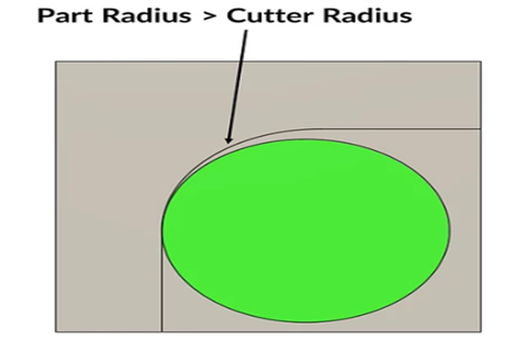
Set the inner edge as large an inner radius as possible and as uniform a radius as possible to avoid cutter changes. The precision can be improved by reducing the number of tool changes. We can think of the cutting parts of the corner as riding a bicycle through a bend, the bigger the bend, the easier it is to turn, but also can get a relatively flat speed. The process of cutter processing is the same, if we can design the inner corner into a large radius, the cutter operation will get a certain amount of space, will not easily shake.
The larger the inner radius, the larger the diameter of the cutter, so that a single machining path can cut more materials, speed up the processing efficiency.
Case Study 2
The following is an example of a part radius more than a cutter radius.
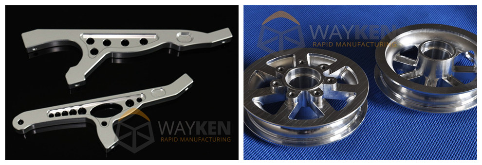
Process: CNC Machining
Material: Aluminum 6061-T6
Customer comment: It’s ok to increase the part radius, it can make it machine easier. No assembled issue. Please help proceed.
Proper Wall Thickness
Reasonable wall thickness design is also important, because too thin thickness may cause parts to break edges or cause deformation. Even if the use of small cutting tools at low speed, also can not avoid the impact of external forces tool oscillation. Therefore, proper wall thickness is more conducive to processing.
Optimization cost:
Reasonable design of wall thickness, metal parts recommended wall thickness of more than 0.8 mm, plastic local small area to more than 0.5 mm. Of course, the specific structure has to be specific analysis, this is not a general principle.
However, it should be noted that in some functional structural areas, it is necessary to increase the wall thickness as much as possible, such as the wall thickness of the threaded hole portion of the wall thickness around the threaded hole portion, because locking screw is an applied force-feeding process and the material thickness is too thin, which may cause the threaded hole to break. For the need for tapping, brass insert holes also need to pay attention to the distribution of material thickness.
Case Study 3
The following is an example of a wall thickness design.
Process: CNC Machining
Material: Aluminum 6061
Finish: As the machine
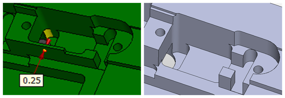
Customer comment: This position requires the installation of the PCB because the size of the PCS is fixed, so the wall thickness at this position can only be reduced and not increased. As the 0.25mm wall thickness cause the brake issue. No problem, we can remove this structure. Do not interfere with assembly components. Please check the modified file as the right picture showed.
Concluding Remarks
Before start prototype or low volume production, we can review the above 3 tips and perhaps get some inspiration. Hope this article was helpful to you and know how we can bring down our project budget. If you want to know more details, please feel free to contact Wayken.