- May 13, 2022
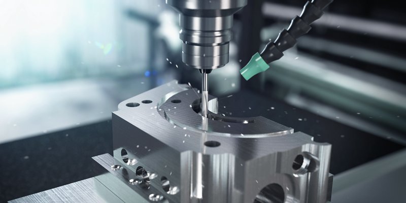
Surface an important aspect of machined parts. The finish of a surface has a significant impact on the durability and performance of a product. So, it is essential to understand surface roughness and its role.
What is Surface Finish/Surface Roughness?
The nature of a surface is known as surface finish or surface topography. It refers to a surface’s minor local deviations from a perfectly flat surface (an actual plane).
The term “surface finish” usually refers to the level of polishing or texturing applied to the surface of a part or component. One of the surface texture parameters is surface roughness. These parameters quantify surface finishing features to regulate the manufacturing process or forecast a component’s behavior during use.
Surface Finish Parameters
Surface finish parameters are also known as surface texture parameters. They are divided into three characteristics, including roughness, waviness, and lay. The roughness is usually composed of smaller irregularities, while the waviness consists of larger undulations. Lay refers to the direction of the dominant grain or texture on the surface.
Importance of Surface Roughness in the Engineering Manufacturing
Here are a few significant reasons for surface roughness’s importance in various manufacturing processes.
• Abnormalities on the surface can act as nucleation sites for cracks or corrosion. Hence, roughness is a strong predictor of a mechanical component’s future performance. Some applications may also be needed to promote adhesion for cosmetic finish coatings such as painting, powder coating, or plating.
• Engineers need to maintain surface control to generate consistent and dependable production procedures for each product. During different surface finishes, surface measuring may be a critical element in maintaining control of the manufacturing process by monitoring it to ensure it is within specific parameters when precise surface engineering is required. The failure of a designed item frequently begins at the surface, either due to a single manufacturing fault or a gradual deterioration in surface quality.
• Surface finish may optimize surface electrical conductions and improve conductivity. It strengthens the product’s resistance to wear while reducing friction and is critical for corrosion and chemical resistance. It also gives the products a distinct visual appeal. Additionally, it aids in the adherence of paints and coatings. As a result, finishing procedures have become the go-to approach for achieving the desired surface finish on various machined and fabricated items.
5 Factors Affecting Surface Finish
When two objects’ surfaces come into touch, the quality of the surface finishes has a significant impact on how well they work and how long they last. Meanwhile, the following are some of the factors that affect surface finish:
Temperature
The volume is affected by temperature. When the temperature rises, metals expand, whereas polymers can be distorted. As a result, the surface finish of a component can be affected by the temperature of the material being cut. Temperatures higher than each material’s optimum for the cutting process frequently result in uneven surfaces and increased surface roughness, especially when utilizing mechanical methods.
Cutting Techniques
Metal blades have traditionally been used in cutting instruments and machinery. Lasers and high-pressure water, on the other hand, have become popular alternatives to traditional mechanical cutting processes. Overall, the new technologies yield more remarkable outcomes, including smooth surface finishes. Laser cutting has numerous advantages over conventional cutting technologies, like greater cutting precision and reduction in rough surfaces. A water jet cutter has benefits, such as higher-performance surface finishing in small parts.
Rate of Material Removal and Feed
The material removal rate (MRR) is the amount of material removed per unit of time. It shows how long it takes to remove a certain amount of material from a workpiece. Feed is defined as the tool’s distance traveled along or into the workpiece for each tool point passed in unit time. Both of these aspects influence the quality of a surface finish.
Cutting Instruments
A component’s surface finish is determined by the manner and quality of the machinery used to cut it. Cutting speed, feed, and depth can all be modified on cutting machines. These variables are changed according to the type of material being cut and the size of the component being created to avoid an overly rough surface.
Cutting Depth and Cutting Rate
Perpendicular to the machined surface, cutting depth is the penetration of the tool’s cutting edge into the material of the workpiece in each pass. Cutting rate is the pace at which a tool’s cutting edge moves across the surface of a workpiece in a given time. The tool may become dull if the cutting speed is too high due to excessive heat buildup. If the cutting speed is prolonged, the machining time will be longer, resulting in decreased productivity.
How to Measure Surface Roughness?
Surface roughness is a way of quantifying the number of irregularities on a surface. The Ra parameter represents the arithmetic average of all surface heights measured across a given area. As mentioned above, they are divided into three characteristics: roughness, waviness, and form These factors can be influenced surface characteristics.
So, There are several ways to measure surface roughness. The main types of measurement techniques are direct measurement, comparison measurement, non-contact measurement, and in-process measurement.
• Direct methods evaluate surface finish by drawing a stylus perpendicular to the surface and drawing it along the surface. Another method for evaluating surface roughness on magnetic materials is inductance. In this method, an inductance pickup uses electromagnetic radiation to measure distances to the test surface. This test yields a parametric value that can be used to compare roughness levels.
• Comparison techniques. Surface roughness samples created by the same equipment, process, and material as the surface to be evaluated are used in comparison techniques. Visual and tactile senses compare a sample with known surface roughness. This technique is best used for non-critical applications due to the subjective nature of the process.
• Instead of using a stylus in contact methods, non-contact methods use sound or light. Optical instruments are divided into numerous categories, including confocal and white light interference. They are distinguished by the principle that underpins them. Electron microscopy techniques are also used, but the equipment used is constrained by their small fields of view.
• In-process methods allow for continuous monitoring of the surface during machining or other processes, which can provide valuable feedback to the operator. In addition, in-process methods maybe provide more accurate results than other methods, due to the fact that they measure the surface under conditions that are closer to the actual application.
Furthermore, the sound is used to determine the surface finish. An ultrasonic pulse is sent to the surface in ultrasonic scattering. The ultrasonic sound waves are transformed and reflected in the testing apparatus. Consequently, the surface roughness characteristics are calculated using the reflected waves.
Light is also able to measure surface roughness by shining a laser beam onto the surface and then measuring the intensity of the reflected light. The rougher the surface, the more scattered the light will be, and the lower the intensity of the reflected light will be.
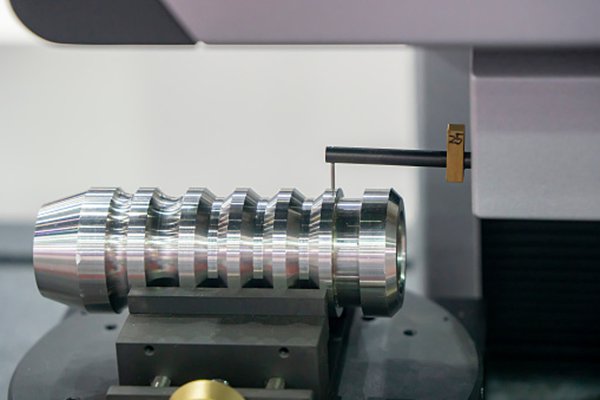
Types of Equipment to Inspect Surface Finish
Numerous methods use different equipment to inspect the surface finish or rough surfaces. Some of the equipment are listed hereunder:
Profiling Technique
The surface is measured using a high-resolution probe. In this procedure, sensitivity is more like a phonograph needle. It’s possible that a CNC probe isn’t effective.
Microscopy Technique
These qualitative approaches focus on comparing and contrasting two different things. The results give useful information regarding the peaks and valleys found on various surfaces.
Area Technique
These methods measure a limited surface area. It provides a statistical average of surface peaks and troughs. Ultrasonic scattering, capacitance probes, optical scattering, and others are examples. Area approaches are easier to automate and implement.
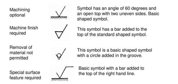
Understanding Surface Roughness Symbols: From RA to RZ
Correctly measuring roughness is critical in engineering applications because surfaces must be within desired roughness limits for quality purposes. Statistical, intense-value, and texture descriptors can all be used to evaluate the finish on a surface.
Ra (average surface roughness)
The most commonly leveraged metric for assessing surface finish refers to Ra or arithmetic mean deviation, which measures a part’s average surface roughness. Ra quantifies the variation of a roughness trajectory from the mean line. Moreover, the Ra surface finish chart is commonly utilized for absolute values when describing, measuring, and duplicating surface topology. Still, it has significant flaws that make additional factors useful.
Rmax (vertical distance from peak to the lowest valley)
Burrs and scratches are the most significant candidates for this roughness characteristic. However, it may not be clear with the Ra machining surface finish chart. Rmax, on the other hand, is extremely sensitive to those irregularities.
Rz (maximum average height of the profile)
Rz typically measures the maximum average height of a surface trajectory. The average outcomes of the five most considerable disparities between the highest peaks and the lowest valleys throughout the entire area determine this parameter. The Ra parameter might be inconsiderate to some extremes, resulting in inaccurate or imprecise measurements; Rz can help eradicate some of these errors.
Center Line Average (CLA)
Center Line average is defined as the arithmetic mean height of peaks and valleys, which a profilometer or optical interferometer determines in the measurement of roughness of surfaces. It is considered to be the most acceptable method of measuring surface roughness.
Ra vs. RMS
As you know, various acronyms are used in machining surface finish symbols, including Ra, Rsk, Rq, Rku, Rz, RMS, etc. They’re units for measuring the quality of a surface’s finish. Micrometers or even microinches are the most common surface finish units. Additionally, the smaller number indicates the finer surface finish. The surface roughness chart below compares the two scales, Ra and RMS, for manufacturing processes.
| Approximate Surface Roughness Conversion Chart | ||||
| Roughness Grade Numbers | American System | Metric System | ||
| Ra(µin) | RMS(µin) | Ra(µm) | RMS(µm) | |
| N12 | 2000 | 2200 | 50 | 55 |
| N11 | 1000 | 1100 | 25 | 27.5 |
| N10 | 500 | 550 | 12.5 | 13.75 |
| N9 | 250 | 275 | 8.3 | 9.13 |
| N8 | 125 | 137.5 | 3.2 | 3.52 |
| N7 | 63 | 69.3 | 1.6 | 1.76 |
| N6 | 32 | 35.2 | 0.8 | 0.88 |
| N5 | 16 | 17.6 | 0.4 | 0.44 |
| N4 | 8 | 8.8 | 0.2 | 0.22 |
| N3 | 4 | 4.4 | 0.1 | 0.11 |
| N2 | 2 | 2.2 | 0.05 | 0.055 |
| N1 | 1 | 1.1 | 0.025 | 0.035 |
How To Select Suitable Surface Roughness for CNC Machining?
CNC machining is an exact and accurate manufacturing method that can produce items with tolerances as low as 0.025 mm. But machining processes may leave cut marks on the end product’s surface. The surface roughness of a part after machining is rarely random.
Instead, steps are taken to ensure that a particular roughness is obtained. It implies that the roughness values on the surface are predetermined. Specific Ra values are considered industry standards in manufacturing, as established in ISO 4287.
During CNC machining, these are the values that can be supplied. They are used in various manufacturing and post-processing procedures and range in size from 25 um to 0.025 um. The lower the Ra value, the more machining effort/operations necessary, hence quality control.
Below are listed some of the Ra values:
3.2 μm Ra
It is the typical finish for commercial machines. It’s acceptable for most consumer parts and smooth surfaces; however, there are visible cut marks.
1.6 μm Ra
With this option, cut marks are usually just marginally apparent. This Ra value is suitable for slow-moving and mild load-bearing surfaces and is suggested for tight fittings and stressed parts.
0.8 μm Ra
This high-end surface finish necessitates meticulous attention to detail, which adds to the expense. It’s essential for parts that are subjected to high levels of stress.
0.4 μm Ra
Surface roughness of this degree necessitates the most work to produce and should only be requested when smoothness is a top priority. It’s ideal for areas subjected to a lot of tension or stress.
Conclusion
Surface finish is the process of creating the desired surface roughness on a fabricated part. It is the result of the manufacturing processes used and can have a major impact on the function, aesthetics, and durability of the final product.
However, achieving precise surface roughness seems not very easy and may be costly. This is where you can find a professional finishing team to help you deal with this challenge. Here, As a one-stop machining manufacturer, WayKen will handle your project with strict surface finish standards with a cost-effective solution.
FAQ
What are the units of Ra?
The units for Ra are micrometer and microinches.
What is a 125 surface finish?
A 125 finish is 0.000125 millionths of an inch.
How is Ra and surface smoothness related?
The lower the value of Ra, the higher would be surface smoothness and vice versa.
What does RMS 63 mean?
RMS 63 indicates that the surface is smoother and has a better finish.