The acronym CNC in the term CNC machine means Computer Numerical Control. Usually, when we think of CNC machining, we imagine the CNC machine tool, but actually, modern CNC machines represent a broader term. Industrial robots and some computer-controlled measuring machines are also CNC machines.
It was the year 1952,due to the need for precise machining of parts in the aviation industry,when John T. Parsons, in collaboration with IMB (International Business Machines Corporation) and MIT (Massachusetts Institute of Technology), developed the first CNC milling machine. From then on, smarter industrial production has become widespread and CNC machining has become available to all industries, along with the rise and use of CNC programming languages – G code and M code.
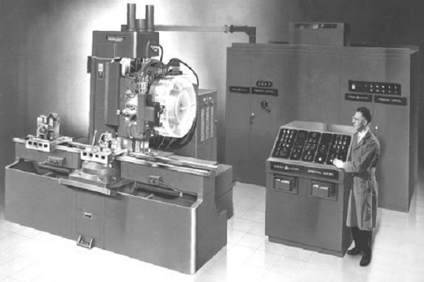
Throughout the 70-year history of the development of CNC machines, various programming languages not only G code and M code, have been used for their programming. Thus, in the beginning, the Parsons’ trailblazer machine was programmed with the help of drilled tapes, and later, in the year 1956, a special programming language (APT programming language) was developed for CNC machining.
RS-274 or better known as G-code, which this article also talks about, was created in the same decade. G-code is developed from APT programming language which contained data about cutter (tool) location or geometry, and other non-geometry machine functions such as spindle speed, cooling, etc. RS-274 functions (G and M codes) inherit the basics from APT programming language with minor modifications that have made programs shorter and more convenient for the machine control unit.
| APT | G and M codes |
| GO TO {X, Y, Z} | G1, G2, G3 {X, Y, Z} |
| FEDRAT | F |
| SPINDLE CW / CCW | S M3 / M4 |
| COOLNT ON / OFF | M8 M9 |
| FINI | M30 |
RS-274 programming language is often called “G code” because it mainly consists of G functions (G codes). But it in itself also contains equally important M functions (M codes). For that reason, it is necessary to define these terms, i.e. to answer the following questions clearly and directly:
- What are G codes?
- What are M codes?
- What are the differences between G code and M code?
Main functions | Description | Auxiliary functions |
G0 | Rapid positioning (linear) | X, Y, Z |
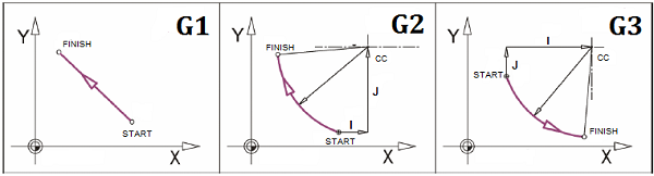
G1 | Linear interpolation | X, Y, Z, F |
G2 | Clockwise circular interpolation | X, Y, Z, I, J, K, F |
G3 | Counter clockwise circular interpolation | X, Y, Z, I, J, K, F |
EXAMPLE 1:
The sentence in G-code: G1 X10 Y50 F100
Explanation: Tool goes linear to wanted point (Coordinates: X=10 mm, Y=50 mm) with the speed of 100 millimeters per second.
The sentence in G-code: G2 X10 Y50 I10 J40 F100
Explanation: Tool goes circular (Clockwise direction) to wanted point (Coordinates: X=10 mm, Y=50 mm) with the speed of 100 millimeters per second; Circle center position relative to the starting point: +10 mm on X-axis and +40 mm on Y-axis
The sentence in G-code: G02 X50 Y10 I40 J-10 F75
Explanation: Tool goes circular (Clockwise direction) to wanted point (Coordinates: X=50 mm, Y=10 mm) with the speed of 75 millimeters per second; Circle center position relative to the starting point: +40 mm on X-axis and -10 mm on Y-axis.
Main function | Description | Auxiliary functions |
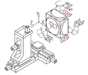
G17 | Select XY for work plane | / |
G18 | Select ZX for work plane | / |
G19 | Select YZ for work plane | / |
G20 | Units: inches (inch) | / |
G21 | Units: millimeters (mm) | / |
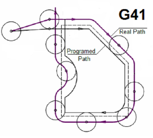
G41 | Tool radius compensation – left | D, X, Y, Z |
G42 | Tool radius compensation – right | D, X, Y, Z |
G40 | Tool radius compensation – off | / |
G43 | Tool height offset compensation | H, Z |
G49 | Tool height offset compensation – off | / |
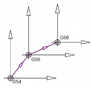
G54 | Machine coordinate system | / |
G55 | Work coordinate systems | / |
G56 | Work coordinate systems | / |
G57 | Work coordinate systems | / |
G58 | Work coordinate systems | / |
G59 | Work coordinate systems | / |

EXAMPLE 2:
Sentence in G-code: G21 G17 G55
Explanation: Setting programming units to millimeters; Selecting XY working plane; Selecting G55 coordinate system
Sentence in G-code: G43 H1 Z100
Explanation: Setting tool height offset compensation to H1 (“H1” is a position where the value of tool height is saved in the memory of CNC machine) and taking a new position (Coordinate: Z=100 mm)
Sentence in G-code: G41 D1 X15
Explanation: Setting left tool radius compensation to D1 (“D1” is a position where the value of tool radius is saved in the memory of CNC machine) and taking a new position (Coordinate: X=15 mm); While tool goes to wanted position, it slowly moves to left, so when tool reaches wanted position tool radius compensation is completed.
Sentence in G-code: G40 G49
Explanation: Canceling tool radius compensation; Canceling tool height offset compensation
Main function | Description | Auxiliary functions |
G90 | Absolute programming: Coordinates relative to work coordinate system | / |
G91 | Incremental programming: Coordinates relative to the coordinate system i in the current position | / |
Main function | Description | Auxiliary functions |
M00 | Program stop | / |
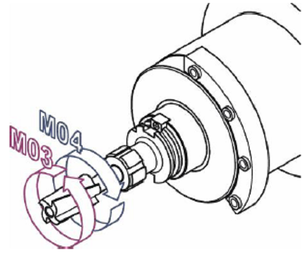
M03 | Spindle On (Clockwise) | S |
M04 | Spindle On (Counterclockwise) | S |
M05 | Spindle Off | / |
M06 | Automation tool change | T |
M08 | Coolant On | / |
M09 | Coolant Off | / |
M30 | End of program | / |
M98 | Subprogram call | “Subprogram name” |
M99 | Return from subprogram | / |
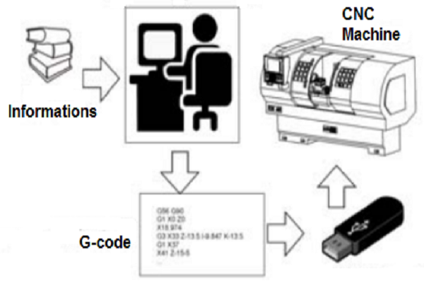
CNC programming is alphanumeric formatting data (G and M codes) on geometry and technology of parts, which needs to be processed on such a machine, but also another programming, which they usually perform machine manufacturers.
Programming CNC machines using G code is mostly sentence-based, which can be seen in previous examples where the explanation of G functions was done as interpreting the sentences of a program written in G code. There are several methods of CNC programming, i.e. generating G and M codes:
- Manual programming,
- Programming in operation and
- Programming using CAD (Computer-Aided Design)/ CAM (Computer-Aided Manufacturing) systems.
Manual Programming
With manual CNC programming, a programmer based on his own knowledge and experience as well available information on machines, tools, machine accessories, processing modes, applying programming instructions, manually writes geometric and technological information required to complete the alphanumeric program. Manual programming can be organized as the following basic activities:
- Defining processing, basing, and tooling plans,
- Translating geometric information with workshop drawing, for route planning purposes
- Tools, and arranging them into blocks according to processing order,
- Writing and completing programs in the form program sheet (G code) and
- Transfer of information from the program sheet to control unit memory
Programming in operation
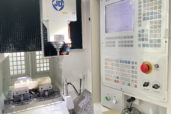
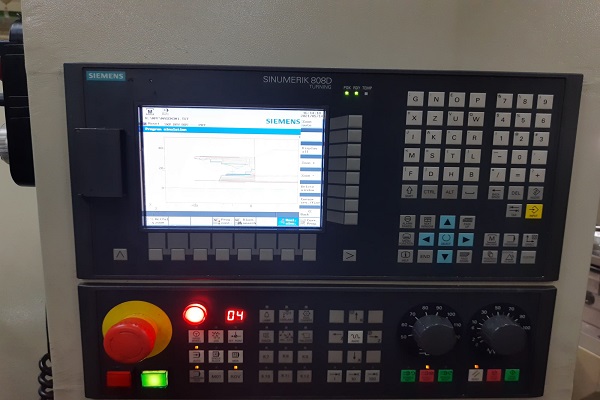
In order to constantly improve the method of CNC programming, as well as the desire to put the programming on the machine itself, in order to still larger and easier applications of CNC, some manufacturers have offered control units that they support programming directly on the machine itself. Although from the very beginning of the application of CNC there was the possibility of immediate programming on the machine in the so-called MDI (Manual Data Input) mode, programming in operation represents a completely new method of programming.
With this method, the Control Unit, which supports it, has integrated additional functions that are avoided classical programming using G code. Programming here comes down to interactive dialogue between the operator and the control unit, via keyboard and graphical user interface, which can generate simple processing contours as well as typed cycles for processing. Control unit based on entered queries, performs the necessary tool path calculations, and automatically generates a G code.
Programming using CAD/CAM systems
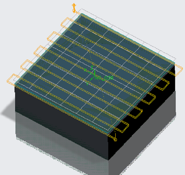
The geometry of the parts, used for example in the aerospace, military, and other industries, is very complex with second-order surfaces, which require multi-axis machining (3-axis, 4-axis, and 5-axis CNC machining). Complex programs for processing such surfaces require several thousand blocks (sentences) whose handwriting is very hard and time-consuming. Therefore, it was necessary to use computers for technological preparation, i.e. programming of CNC machines for machining the above-mentioned parts on the basis of G code and M code.
CAD / CAM programming can be classified as computer CNC programming. The integration of CAD and CAM has led to improvements in NC programming, especially in terms of programming simplification. Now the programmer doesn’t have to think about defining geometry, that’s what CAD / CAM software does. What remains for the programmer is that through active interaction with the system in the program, he adds other technical information such as grips, basing, clamping, cutting tools, and processing modes. It should be emphasized that there is an integration of CAD / CAM and CAPP (Computer Aided Process Planning), which develops a solution for these requirements as well.
This is what the Procedure for programming a machine in a CAD / CAM environment looks like:
- Modeling of CAD models,
- Processing planning using available CAM strategies for processing and calculating tool paths and obtaining CL (Cutter Location) file,
- Tool path simulation and material removal simulation for program verification and detection of possible errors and collisions,
- Post processing the CL file and obtaining the G code using the postprocessor for the selected machine,
- Transfer the G code to the control unit. Preparation of tools and workpieces. Base the workpiece on the machine,
- Check processing conditions and modes, check speeds and accelerations, which can significantly affect the quality of processing and
- Machining of a workpiece on a machine.