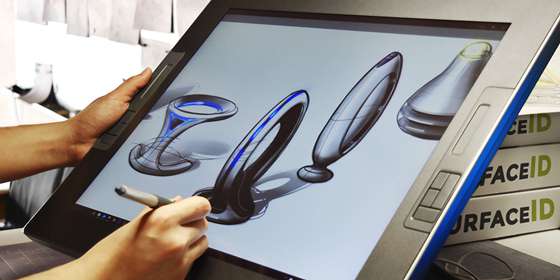
Here are some basic rules to take into consideration when designing CNC machining.
- Design parts for easy machining by tools of large diameter, as this helps ensure faster processing while ensuring you do not require specialist tools;
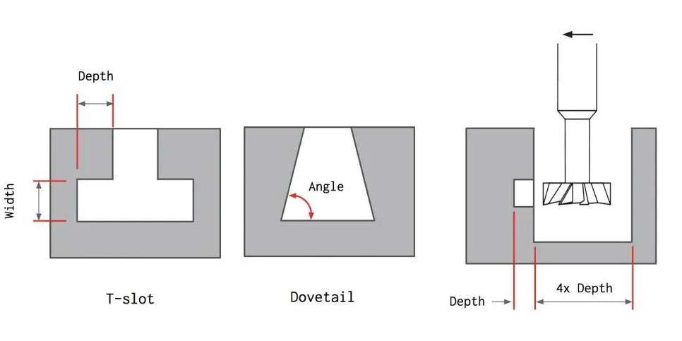
- Cavities should not be more than four times deeper than their width, as it makes machining a tad more difficult;
- Take into consideration the principal direction your machine allows as well as its standard number of axes when making your design to avoid complications;
- Do not use sizes below 20 points when machining text to avoid mistakes within the engraved text.
In the CNC machining world, no set of standards is generally accepted. This is primarily because the industry and the machines used are always evolving. However, some best practices and recommendations would help ensure your design quality remains top-notch. These recommendations include;
1. Internal Edges
The vertical corner radius should be at least one-third of the cavity depth when creating inner edges. You can use a diameter tool that has the advised cavity depth if you use the indicated corner radii.
Corner radii slightly above the advised value allow you to cut along a circular path as opposed to a 90-degree angle, producing a surface finish with a better level of quality. It is advised to employ a T-bone undercut rather than reducing the corner radius if you require a 90-degree angle instead.
2. Holes
To create holes, machinists may utilize drill bits or end mill equipment. It is best to use standard drill bit sizes, measured in either metric or imperial units, as a guide when determining the diameter of the holes in your design.
Technically, any dimension greater than one millimeter is feasible. Machine operators use reamers and boring equipment to complete holes that need to be within precise tolerances. It is best to utilize a standard diameter for holes that require great accuracy and are smaller than 20 millimeters.
When designing parts for CNC machining, four times the nominal diameter is the maximum proposed depth for any hole, but 40 times this amount is doable. The nominal diameter is typically 10 times the ratio.
3. Threads
The minimal thread size used when developing CNC-machined items is M2, but M6 or above is usually ideal. Machinists can limit the danger of tap breakage by using CNC threading machines to cut threads as small as M6.
The minimum thread length should be 1.5 times the nominal diameter, while the recommended length is three times the normal. For any thread less than M6, you must add an unthreaded length at the bottom of the hole that is 1.5 times the nominal diameter. Threading the hole throughout its length is best for threads larger than M6.
4. Cavities and Pockets
Since end mill tools have a restriction on their cutting length, the industry-recommended cavity depth on any design is four times its width. A lower depth-to-width ratio would result in greater chip evacuation, tool deflection, and vibration.
Does your CNC design require larger depths? One way to solve this challenge is by using a variable cavity depth and a specialized tool.
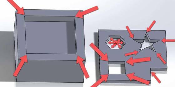
5. Small or Raised Text
You may need to mark parts with part numbers or company names. Adding text looks really cool in the custom CNC design, but is time-consuming to process. Electrochemical etching or laser marking is usually better.
Maintaining best practices as well as knowing the CNC machining basics helps ensure part or product is of high quality. With that in mind, here are some best practices you need to keep in mind when designing parts for CNC machining according to the machining type.
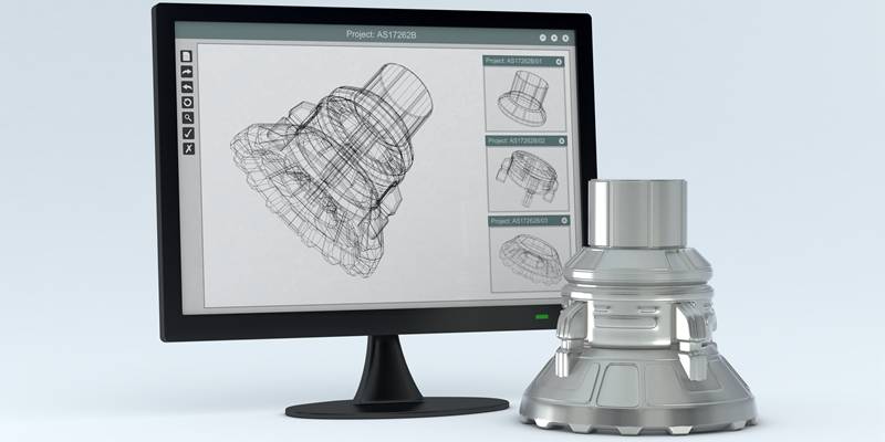
1. Design for CNC Milling
CNC milling is a machining technique of rapidly removing material from raw material using round cutters to obtain a desired shape. The mill machines come in many different designs, ranging from 3-axis to 12-axis.
1.1 Commonly Available Cutting Tools
Consider the many tools frequently accessible for CNC milling while creating your CNC parts design ideas, such as end mill cutters. Cost and lead time would reduce considerably if it is possible to produce the required features and geometry by using common tools.
Also, consider tool standard sizes when creating your design, as a design with a radius smaller than the standard would result in design complications and cost.
1.2 Avoid Sharp Internal Corners
It is impossible to achieve sharp corners with a milling tool. The reason is that the cutting tool used here is round. To use a CNC mill, your corners need to have radii, which must be larger than the cutter used in creating them. Ideally, the diameter of the cutting tool will be twice the radius it is making.
Filets are also necessary when a sloped or drafted surface meets a vertical wall or sharp edge. Unless the surface is flat and normal to the tool, a square or ball end mill will always leave material between the wall and the below surface.
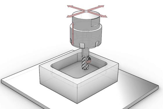
1.3 Avoid Deep Narrow Slots
Lengthy tools often vibrate and deflect, which results in a poor surface finish. Hence, an endmill’s final depth of cut should not be more than 15 times its diameter for cutting plastic, 10 times its diameter for cutting aluminum, and 5 times its diameter for cutting steel.
For instance, a slot cut on a machined steel item with a 0.5″ end mill that is 0.55″ wide should not be deeper than 2.75″. Since the internal filet radius, the previous point, also depends on the tool diameter in this case, any internal radii should be bigger than 0.25″.
1.4 Design with The Largest Possible Internal Radii
A bigger cutter equals more material removal per time, which reduces machining time and costs. Always use the maximum internal radii permitted while designing. When feasible, stay away from radii smaller than 0.8mm.
Also, make your filets slightly larger than the endmill’s radius; for instance, use a radius of 0.130″ (3.3mm) rather than 0.125″ (3.175mm). The mill will follow a smoother route, giving the surface a finer polish.

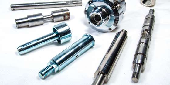
2. Design for CNC Turning
CNC turning is a machining process that creates parts with axial symmetry and cylindrical geometry on a lathe. The process involves holding the workpiece on a rotating chuck while the cutting tool cuts it to desired shape. This machining process results in a better surface finish and tighter tolerances.
Here are some tips for making a design for CNC cutting using a turning machine
2.2 Avoid Sharp Internal and External Corners
When designing for CNC machining, it is important to avoid sharp corners, both within and outside. Adding a radius to the internal corner is one way to ensure that the tool does not run up a bigger surface. Another way to avoid sharp internal corners is to slant a steep sidewall slightly. With fewer processes required, it may be simpler to machine contours with a single lathe cutting tool.
2.3 Avoid Long, Thin Parts
Avoid utilizing long, thin-turned pieces since they are more likely to spin unevenly and chatter against the tool. When making a lengthy component, try to leave room for a center drill on the free end and utilize a center to keep the part spinning straight. Besides, Keep the length-to-diameter ratio at 8:1 or less as a general guideline.
2.4 Avoid Thin Walls
Similar to milling, excessive material removal can cause unnecessary stress on the component. Too thin walls will also reduce rigidity. However, thin walls make tight tolerances challenging to maintain. This is why it is best to keep the wall thickness of turned sections above 0.02 inches in your design for CNC machining.
2.5 Feature Symmetry
Every feature added to a turned part generally needs to be symmetrical around the turning axis. It will take more complicated machining and setups to add geometry or features that are not axially symmetric. Steps, tapers, chamfers, and curves are characteristics that are excellent for turning.
It is occasionally necessary to add characteristics to a turned part that are not axially symmetric, which may necessitate a different operation. You can keep a bit of symmetry even when this is required.
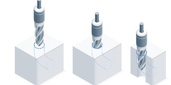
3. Design for Drilling
This is the term used for operations that involve creating holes in workpieces. Tools used in this operation feature a conical tip, which allows them to dive deeply into materials during machining.
Consider the following suggestions when creating a design intended for CNC drilling.
3.1 Appropriate Hole Depth
Drilling should never go deeper than 12 times the closest bit diameter. The reason is that drill bits that are this long or longer lose stiffness, lose the ability to maintain a tight tolerance, and are more likely to break. Also, consider making the hole diameter larger if you need to dig deeper.
However, if a deep hole is essential, another alternative is to drill from both sides of the part. Keep in mind that since a second machining setup will be required, the manufacturing process will take longer and cost more.
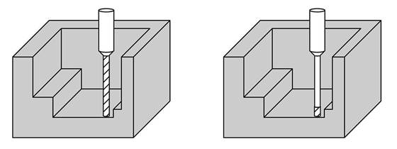
3.2 Avoid Partial Holes
Since there is a great likelihood that the tip will wander, It is best to avoid partial holes. But, if only a portion of the hole is necessary, keep the drill axis on the material such that the component will hold most of the hole.
3.3 Keep Drill Axis Perpendicular to the Surface
The drill axis should be perpendicular to the surface to prevent tip wander. A shallow, flat-bottomed pocket machined onto the surface of a round object frequently allows the drill to enter perpendicular to the part’s surface. It is best to use a pilot hole to solve this challenge, although making this choice would become necessary during CNC machine programming rather than CNC part design.
3.4 Avoid Drilling Through Cavities
Be sure no cavities already exist in the part when planning the locations of your drilled holes in your CNC design ideas. The drilled hole can slightly intersect the cavity if it is necessary, provided that the hole’s central axis does so.