- November 1, 2021
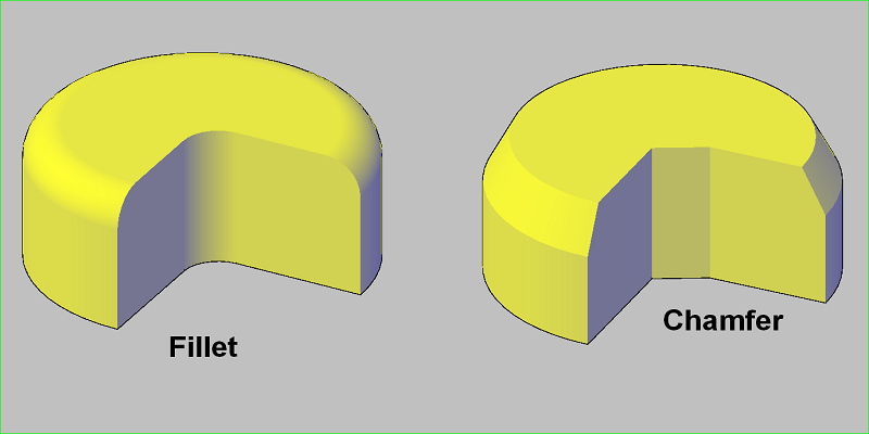
When we compare a fillet vs. chamfer, most people think about the geometric difference between fillet and chamfer, but it is not so easy to define chamfer vs. fillet.
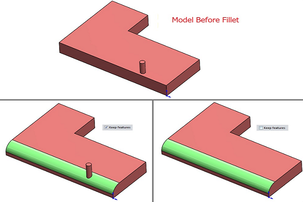
What is The Fillet?
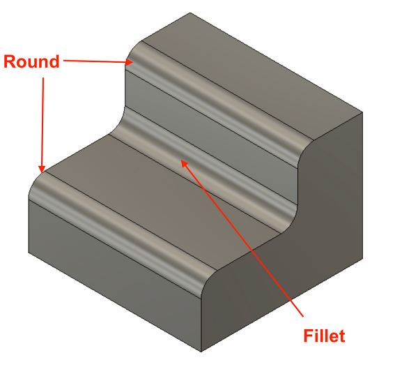
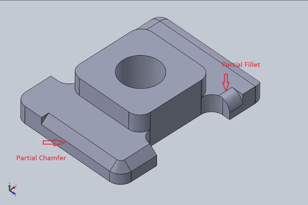
In fillet engineering, fillets generally refer to rounding the interior or exterior corner of a part. It is an edge and rounded corner of a piece and maybe inside or outside of the part.
When we define fillet, the Exterior fillet is convex, and the inlet fillet is concave. The primary purpose of their uses is for the lower stress concentration factor and uniform distribution of stress.
According to fillet definition, a fillet generally is rounded edges or corners, and rounding of an interior corner is called fillet radii. Fillet radii can employ on casting to improve the quality and also use for the increment of load-bearing strength. Therefore fillet radius is a standard allowance in a casting design.
Fillet AutoCAD
The fillet and chamfer command in Auto Cad definition modify a pair of objects, whereas chamfer can create a beveled corner, and a fillet can create a curved corner in the middle of two lines.
What is the Chamfer?
The chamfer is a sloped or angled corner or edge, mainly used to keep the edge safe from damage and give a more uniform look to the rough edge. Let’ see what does a chamfered edge look like and why does fillet engineering use chamfers for high-stress concentration edges?
Champer edges are sharp and straight, rather than smooth edges, and are used for low-stress concentration as they can deform the material. So it is not recommended for high-stress concentration edges. For any design, you must have knowledge of chamfer edge vs. bevel edge and the function of champer in AutoCAD to make a comparison and sound decision. A bevel is a sloped edge on top and a champer has a beveled edge on the bottom that can connect with two surfaces.
What are the chamfered edges?
A chamfer is an angled or sloped edge or type of bevel. In mechanical engineering, we can classify champer into two subgroups:
1. Chamfer with 45-degree use for removing bur in the drilling operation. The chamfers allow a bolt to sit below the flush fir surface rather than sticking out.
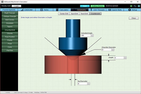
2. Chamfer with 60 degrees has sharp corners and is not much effective in reducing stress concentration. They use as a lead-in for a bolt and screw. The chamfering is essential after the parts finishing process to make a furrow, groove, or bevel.
When will you need fillets and chamfers?
Choosing between a fillet mechanic and chamfer molding can increase parts efficiency and prove cost-effective. It would be best to choose according to your design and manufacturability; otherwise, a wrong decision can cost you more and decrease the part service life.
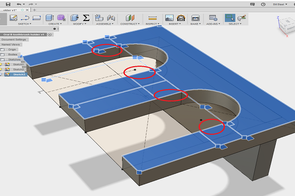
You should be aware of when to use fillets Solidworks and the best usage of chamfer Solidworks. So let’ go through the whole discussion when you need fillets and chamfers.
1: You can use a chamfer for a hole where you need to drive bolt or screws. The sharp chamfered edge can be helpful for smooth pin movement and fastener insertion. So on a hole or around the edge of the hole, chamfer use is a good decision. A fillet can prevent the smoother pin movement of screw and bolt.
2: Fillet engineering finds it challenging to decide on selecting a chamfer or fillet with the edges. Sharp edges are not safe to use and can damage their users, so it’s critical to remove all sharp edges.
3: Fillet and chamfer both can use for outside edges. It depends on the design requirements and needs. Simple chamfering can employ to break sharp corners, but it should be safe for your design. Breakage of sharp edges can reduce the risk of injuries.
4: Fillet tool is best to use across the edges of a part. It is suitable for designing exterior part which needs an aesthetically pleasing effect. Keep in mind how much higher the use of radius will make a better design. An increased radius fillet can prove effective in stress-relieving.
5: CNC milling parts manufacturing makes it difficult to make sharp internal corners because of material carved out by a spinning tool. This tool leaves a radius while turning at corners; therefore, you can use a fillet inside vertical edges. A bigger radius of internal edges than the cutting tool is a good practice in machining procedures.
6: When we discuss what is chamfered edge and chamfered corner? Chamfered edge, chamfered hole, the chamfered surface can use depending on design requirements. Simple chamfering can break the sharp corners but make sure your exterior is not critical in your design. According to chamfering operation definition, it is a general machining practice.
7: For sloped and angled surfaces, you have to keep in mind the process of how counter can machine in 3 axis machines. 3D machining recommends angular surfaces, and to be more aesthetically appealing to your product, and you need fillets all around the edges.
How do you decide on fillet radius? It is a very critical decision in designing. According to the fillet radius definition, a big radius can create minor complications, so you have to consider radius size while choosing a round fillet.
Differences between Fillet and Chamfer
Some main difference between a fillet and a chamfer are as follow:
● Fillets need a specific size of tooling for the production of various fillet radii. On the other side, chamfer doesn’t need any particular size of tooling. To make different chamfer sizes, one size of tool will be sufficient for the process.
● When we consider the production costs of the machining process, the chamfer is less expensive compared to fillets. So it proves more costly for parts fabrication.
● Fillets are safe to use as they don’t have sharp edges. Champers have sharp edges and need to be carefully used in any operation.
● Fillets have a better stress flow, can share stress on a large radius, and protect from deforming, so fillets are a smart choice for the exterior parts. Chamfers have less stress concentration and can be a cause of material deformation.
● Fillet engineering requires more machining time as compared to chamfer engineering. Fillet edges and fillet corners are not easy to make and require more time and effort.
● Fillets have curved edges that take more time and are challenging to create. Casting and forging are easy processes for fillet creation. The chamfer is a fast method and doesn’t require much time for machining.
How to Choose Between Fillet and Chamfer
Choosing a fillet or chamfer is not like choosing a car and book. You have to keep in mind some prominent points, and your concept of fillet and chamfer should be clear. Is it not?
Chamfer AutoCAD command and fillet command are mainly used to modify ribbon. This command is famous due to its fast and best-generated result. Let’s see the points on how you can choose between chamfer and fillet. They both perform the same function, but their selection depends on how you manufacture components.
Some main points are as under:
- We need a single tool for creating different chamfers, but for creating different radii, different radii of tools are at stake for the process.
- A chamfer is a good choice for machining parts from a bar or block.
- When we process manually, a chamfer may require less machining time than a fillet that requires more machining time.
- Fillets are given preference in industrial design due to their visually pleasing characteristics.
- For CNC machining manufacturing, both fillet and chamfer require the same operational time, and you only need to change the tool for CNC machining fabrication.
- Hole function in part design can help to make a selection between a fillet and chamfers. If the hole is for pin insertion, bolt into a part, and drive screw, your choice should be chamfer.
- Chamfers consider a good choice for high machining as it is less costly as compared to fillets.
- Fillet has a uniform distribution of coating and paint. So engineers choose fillet for protective coating. Chamfers have sharp corners, and they reduce the thickness of the layer. Therefore chamfers are not recommended for protective coating and paint.
- Fillets provide lower stress concentration and less resistance compared to chamfers.
- One main disadvantage of chamfers is the non-uniform distribution which results in accelerated rusting.
- Fillets are suitable for the solution of stress concentration- a big issue in load-bearing mechanical parts. We can reduce it by applying fillets on lines and points of high-stress areas. Fillet can distribute the stress effectively and helps to make more durable parts. It also increases the capability of the part to bear a more significant load.
Conclusion
Fillets have lower stress concentration factors, can protect from deforming, while chamfers are more forgiving in chamfer mating parts. So understanding the difference between chamfer definition and fillet definition engineering is very important for you to choose the right design and machining operation for your project. Comparing chamfer vs. fillet vs. bevel can lead to high quality, more efficient design at less cost.
If you are confused about “fillet and chamfer”, here at WayKen, with years of extensive experience in design engineering and part manufacturing, our mechanical engineers will always choose the right method for your machined parts, so you can be confident that your design will perform well during the manufacturing process. Upload your files and let’s get started.