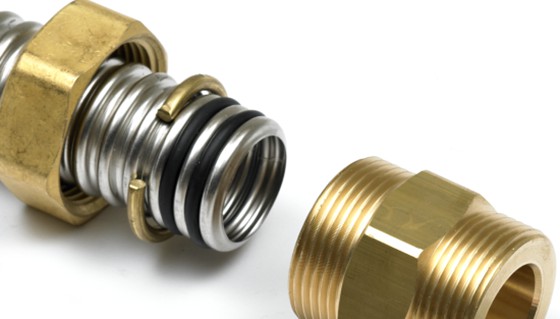
O-rings are mechanical seals that provide high-quality sealing between two mating surfaces. This means that they are responsible for blocking the flow of things from one side of the seal to the other. Consider a pump for example. Its outlet contains high-temperature, high-pressure fluids which can easily escape to the low-pressure compartment, decreasing the pump’s efficiency. Installing O-rings at locations where the fluid can leak prevents this by providing a strong seal.
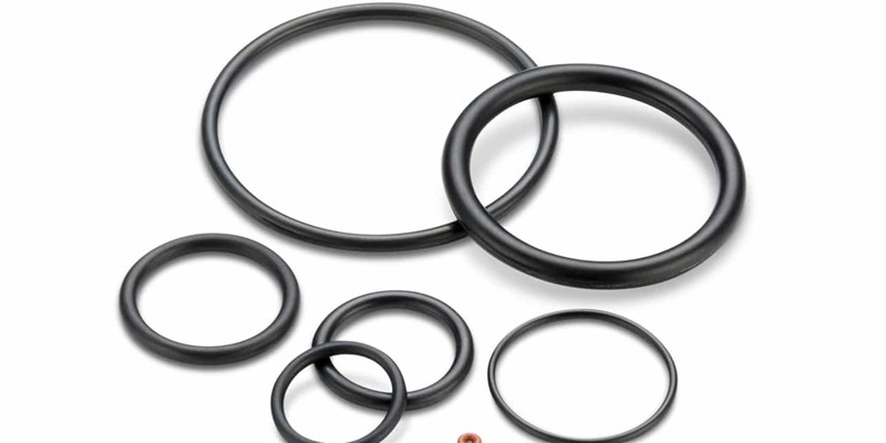
In addition, O-rings come in the shape of a ring, most often with a circular cross-section. They are generally manufactured with a flexible elastomer as flexibility is the most important material property for O-rings to work efficiently.
O-rings also can provide both static and dynamic sealing. In a static seal, both mating surfaces are stationary while in a dynamic seal, there is relative motion between them.
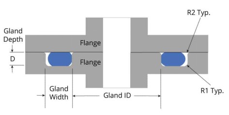
The working principle of the O-ring groove design is simple. The assemblage of both mating surfaces squeezes the O-ring in between them, creating a tight seal. To facilitate this, the inner mating component has a groove machined into its surface at the spot where sealing is required. Engineers call this groove the O-ring groove (O-ring gland).
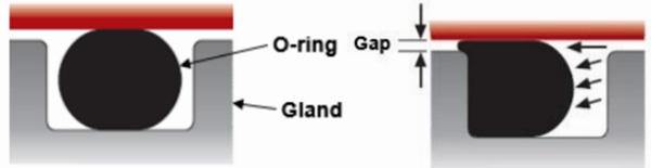
The O-ring groove dimensions require the O-ring to slightly stretch to achieve a sturdy O-ring fit in the groove, quite similar to a snap-fit joint. Moreover, the diameter of the O-ring is intentionally kept slightly larger than the depth of the O-ring groove size, which causes it to extend beyond the mating surface.
This extended part comes in contact with the outer mating surface when it is assembled. The assembly pressure compresses the O-ring to such an extent that it partially fills up the O-ring groove (O-ring gland) and seals the gap between both surfaces. This gap is another important design consideration. Engineers use the term ‘clearance gap’ to describe it.
The o-ring groove (O-ring gland) is the most important design feature for producing efficient O-rings. They come in different shapes and sizes depending upon the exact applications. We highlight some of the main O-ring groove types here.
Flange/Face Seal Groove
The flange seal groove is the most common and simple among the O-ring groove types. The groove is rectangular in shape and has no gap between the mating surface. Thus, there is direct surface-to-surface contact, eliminating any issues related to ring extrusion gaps.
Moreover, flange seal groove is a static O-ring groove design suitable for non-moving components. The table below shows the recommended O-ring groove dimensions for different sizes as per AS568 standards.
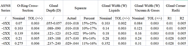
Dovetail Groove
The dovetail groove has inclined sidewalls, making it look like a dovetail, hence the name. The wall inclination creates a groove with a trapezium cross-section, whose main purpose is to hold the O-ring in during installation and maintenance. This design is suitable for static sealing. Moreover, the locking capability makes the dovetail groove ideal for applications with regular disassembly and maintenance, allowing for less downtime and quicker handling.
However, designers must be careful in selecting the dovetail groove dimensions as a large inclination angle can limit the space inside the groove for the O-ring to expand into. If this is the case, lack of space can damage the O-ring and affect the quality of sealing. The table below summarizes the recommended dimensions of a dovetail O-ring groove (O-ring gland) for various O-ring sizes.
| O’ring CS | Groove Depth (L) | Squeeze (%) | Groove Width (G) | Retainer Radius (R) | Groove Radius (R₁) |
| 0.07 | .053 – .055 | 23 | .057 – .061 | 0.005 | 0.015 |
| ±.003 | |||||
| 0.103 | .081 – .083 | 21 | .083 – .087 | 0.01 | 0.015 |
| ±.003 | |||||
| 0.139 | .111 – .113 | 20 | .113 – .117 | 0.01 | 0.031 |
| ±.004 | |||||
| 0.21 | .171 – .173 | 18 | .171 – .175 | 0.015 | 0.031 |
| ±.005 | |||||
| 0.275 | .231 – .234 | 16 | .231 – .235 | 0.015 | 0.062 |
| ±.006 | |||||
| 0.375 | .315 – .319 | 16 | .315 – .319 | 0.02 | 0.093 |
| ±.007 |
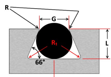
Half Dovetail Groove
The half dovetail groove is a special groove with only one inclined sidewall. It is a compromise between the design advantages of the flange seal groove and the retaining capability of the dovetail groove. Thus, it offers the benefits of both, but to a balanced degree. For example, in applications where the O-ring operates in a vacuum, the O-ring is pulled to one side of the gland. In this case, the flat side of the half-dovetail groove is perfect for holding the O-ring while the inclined side keeps it inside the groove.
As before, the table for recommended dimensions is given below.
| O’ring CS | Groove Depth (L) | Squeeze (%) | Groove Width (G) | Retainer Radius (R) | Groove Radius (R₁) |
| 0.07 | .053 – .055 | 23 | .064 – .066 | 0.005 | 0.015 |
| ±.003 | |||||
| 0.103 | .083 – .085 | 19 | .095 – .097 | 0.01 | 0.015 |
| ±.003 | |||||
| 0.139 | .113 – .115 | 18 | .124 – .128 | 0.01 | 0.031 |
| ±.004 | |||||
| 0.21 | .173 – .176 | 17 | .190 – .193 | 0.015 | 0.031 |
| ±.005 | |||||
| 0.275 | .234 – .238 | 15 | .255 – .257 | 0.015 | 0.062 |
| ±.006 | |||||
| 0.375 | .319 – .323 | 14 | .350 – .358 | 0.02 | 0.093 |
| ±.007 |
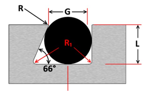
Triangular Crush Groove
This design has a triangular cross-section with the groove machined into one of the mating components. It allows for a simple, cheap grooving process with adequate sealing capacity. The seal is static and also non-reusable. If it is subjected to extreme, uneven compression can permanently deform the O-ring. The O-ring groove dimensions recommended by design engineers are given below for different O-ring cross-section sizes.
| Cross Section (W) | ± | Groove Depth (L) | ± (-0) |
| .070″ | ±.003″ | 0.092″ | +.003″ |
| .103″ | ±.003″ | 0.136″ | +.005″ |
| .139″ | ±.004″ | 0.184″ | +.007″ |
| .210″ | ±.005″ | 0.277″ | +.010″ |
| .275″ | ±.006″ | 0.363″ | +.015″ |
| 1.50mm | ±0.08mm | 1.98mm | +0.08mm |
| 2.00mm | ±0.08mm | 2.64mm | +0.08mm |
| 2.50mm | ±0.08mm | 3.30mm | +0.13mm |
| 3.00mm | ±0.10mm | 3.96mm | +0.13mm |
| 4.00mm | ±0.13mm | 5.28mm | +0.18mm |
The inner diameter (ID) and outer diameter (OD) are important O-ring groove dimensions as they determine the nature of the interaction between the O-ring and the mating surfaces. Moreover, they are also useful in controlling the compression and friction forces the O-ring experiences.
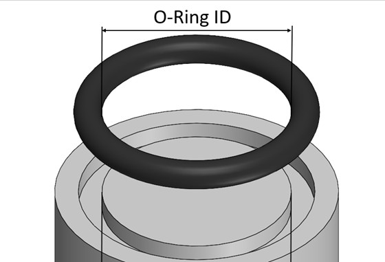
For the ID, experts recommend keeping it 1%-5% smaller than the outer diameter of the O-ring groove (O-ring gland). This allows for the slight stretch of the O-ring during the installation we mentioned at the start.
The OD should ideally be larger than the gland depth by a small amount. This allows achieving proper O-ring compression to occur post-installation. The goal is to have around 1%-3% compression.
The compression set (squeeze) is a critical design consideration in O-ring groove design. Geometrically, it is the difference between the cross-sectional width of the O-ring and the gland height. In other words, it is the length by which the assembly squeezes the O-ring.
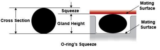
If the O-ring groove size has a large squeeze, there is a risk of over-compressing the O-ring, which can lead to permanent deformation or even failure to create adequate sealing. On the contrary, a smaller compression can is also problematic as it may not create enough surface traction to create the seal.
The O-ring groove (O-ring gland) has numerous benefits over other sealing methods. We briefly touch upon these benefits below.
Reliable Sealing
O-rings are, without a doubt, highly reliable seals. With so many O-ring groove types and materials, designers can pick the best combination for their sealing applications. O-rings rarely fail, have a long service life, and can operate in tough conditions, which is enough to rank them in high-end sealing solutions.
Compact Installation
Among conventional sealing solutions, the compact geometry of the O-ring groove design stands out. Gaskets require a large surface area, and labyrinth seals require extra hardware and space, but O-rings take up minimal space in an assembly and are easy to install.
Lightweight
A major advantage of O-rings is their negligible mass. They are small rings of rubber that hardly add any weight to the assembly but provide good sealing.
Variety of Designs and Materials
The immense variety in material choices and the versatility of O-ring groove design have been discussed above, but we would like to reiterate this point as another huge benefit. Generally, such variety is not available to design engineers, and it is a luxury that they have several options to pick from for such an essential application.
The previous sections discuss in detail the dimensions of the O-ring groove (O-ring gland). In this section, we expand upon those points and offer some advice on calculating the main O-ring groove dimensions, which are the gland height and width.
O-Ring Groove Height
The main parameters determining the O-ring gland height are the preferable amount of compression ratio and the cross-sectional width of the O-ring. Since these two are linked, the formula derives from their shared relationship.
Gland Height = Cross Section Width – ( Compression Ration – Cross Section Width )
The third input is the compression ratio, which is a design decision. Ideally, engineers try to design an assembly with an approximate compression ratio of 20%.
O-Ring Gland Width
The major parameters influencing the O-ring gland width are the O-ring cross-sectional area and the desired fill volume. We suggested that the O-ring fill must be below 85% in a previous section. Keeping this in mind, engineers normally target a value between 50%-85% based on their application, material choice, temperature conditions, etc.
The generalized formula for O-ring gland width:
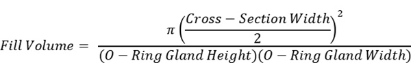
Note that this is not the direct formula for the O-ring gland width but a general guide for designers to get acquainted with the basic geometry of the O-ring groove design. In reality, there are numerous correction factors for variables like thermal expansion that fine-tune the calculations.