Sheet metal cutting refers to the application of a significant force on the sheet which eventually causes it to break into parts. The most common method of cutting is by shearing, in which a shearing force greater than the ultimate shear strength of the material is applied, causing it to fail and separate at that location.
Common defects include:
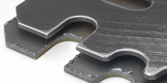
1. Burred and Deformed Edges
Burred edges are sharp, uneven metal pieces that remain attached to a sheared metal workpiece. They usually arise due to blunt blades, or improper positioning thereof. Too large a clearance between blades will cause them to tear instead of shear, while a smaller clearance will prevent the blades from cutting through the material, producing burrs.
Similarly, deformed edges are formed due to faulty clamp pressures, in addition to the improper positioning of blades.
To prevent this, the shear machine’s manual can be referred to obtain the correct clearance and clamp pressure according to the material type and thickness.
2. Twisting
After completing a shearing process, the metal may have experienced some twisting along its axis. This is caused by cutting too narrow strips or using the incorrect rake angle. This can be avoided by adjusting the rake angle depending on the sheet metal’s properties, geometry, and cutting parameters.
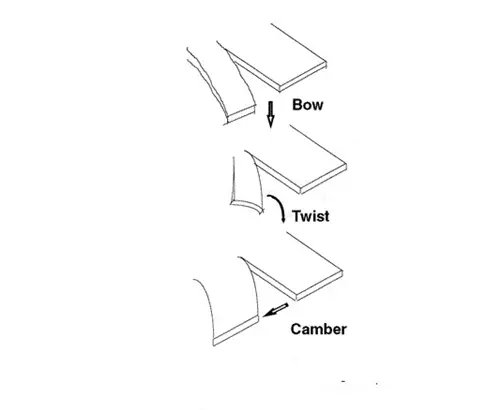
3. Cambering
Cambering is observed when the sheet metal workpiece has a varying thickness along its width. This occurs when it moves in a horizontal direction, but without twisting or lifting along its edges. The result is a concave, convex, and triangular-shaped metal. This defect can be minimized early on by shifting the direction of the metal grains, and by changing the rake angle.
4. Bowing
Bowing occurs when the edges slightly rise from the plane due to inappropriate shearing. It is commonly observed in long, narrow, thin sheets. To overcome this, the rake angle should be decreased as much as possible, and the sheet metal must be held with back support.
The sheet metal stamping process is a cold-forming manufacturing process where a die is used on a press machine to punch an impression on a metallic blank shape, thus forming plastic deformation. This process may also be accompanied by other forming tools to obtain a completed piece or as an intermediate step.
1. Splits
Sometimes when the metal layers are pushed past their workability limits, they start to thin until the flat layer tears along the weakest area. Such defects are known as ‘necking’ or ‘splitting’ in the sheet metal stamping process.
To ensure this does not occur, forming simulation software should be used to analyze the sheet before the operation is started. Furthermore, examining the form radius and depth settings, the type, and thickness of the material, and the heat treatment techniques can also help to avoid these defects.
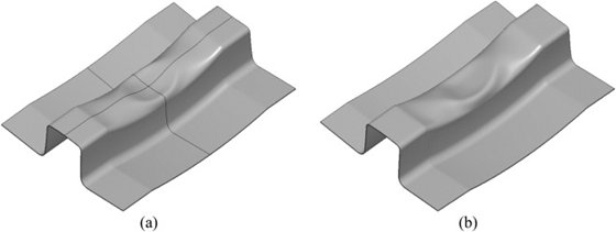
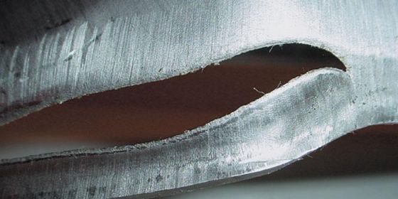
2. Wrinkles
When the compressive strain conditions applied by the processing equipment push the sheet metal upon itself, the linear force is crushed inwards until a wrinkled flange is obtained and the internal geometry is damaged.
Such defects can be countered by stretching or drawing the sheets instead of forming them. Moreover, draw beads, draw binders, and pads can be utilized when the sheet has an intricate geometric profile. Furthermore, draw beads help control the flow of metal into the die cavity.
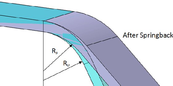
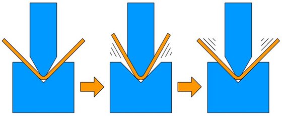
3. Springback
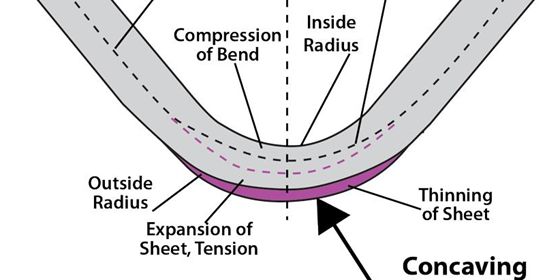
When the bend radius falls below the set value imposed by the bending equipment, the desired shape is not achieved. This is known as spring back, or final part deviation due to an incorrect process.
To correct these defects, include an overbend or overcompensation adjustment. However, doing so does not eliminate the elastic deformation error, increasing the stiffness of the part by positive stretching.
Sheet metal bending is an important sheet metal process due to its ability to draw a variety of part geometries without tooling, as well as fast lead times, high repeatability, and automation. It also allows products to be manufactured from one piece of metal, utilizing plastic deformation, as opposed to multiple pieces joined together via welding or riveting, thus resulting in lower costs, improved strength, and simplified assembly.
1. Cracks in the bending angle
The two major reasons for cracks in a drawn part are poor metal pliability and having a very small bending radius.
To avoid the occurrence of these defects, use softer metals, or increase their malleability by heating and then cooling them slowly.
2. Unstable bending angle
Primary causes for such defects are insufficient material pressure and irregular bending pressure causing irregular compressive buckling. Asymmetric convex-concave die fillet may also contribute to this problem.
To solve this, increase the jacking force and balance out the clearance in the convex-concave die fillet.
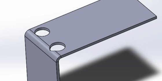
3. Hole deformation
The location of the hole can be deformed by the friction between the concave die surface and the outside surface during the bending process.
Such defects can be resolved by raising the pressure of the ejector plate or by adding a hard spot on this plate to increase the friction between the aforementioned surfaces so that they do not slide.
4. Uneven concave piece bottom
Such defects are usually caused by the use of an ejection device, due to insufficient force or uneven material.
Therefore, ensure that the ejection device is set to the correct measure of force, or removed altogether and that the material is evenly leveled before the start of the bending process.
5. Non-parallel bend to the middle of the holes
This defect is caused by the bending height being less than the minimum bending height limit, which causes the curve to expand and become distorted.
Simply raising the height of the bending piece or the material will solve these types of defects.
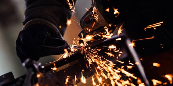
Welding is commonly used to join two or more pieces of sheet metal together. Be it MIG Welding (Gas Metal Arc Welding), TIG Welding (Gas Tungsten Arc Welding), Shielded Metal Arc Welding (SMAW), or Flux Cored Arc Welding (FCAW), several defects may be faced if the proper technique is not used.
Common defects in the sheet metal welding process include:
1. Spatter
Spatter occurs when molten material droplets are formed near the welding arc. It is usually caused by high currents, wrong polarity, or insufficient gas shielding.
To avoid it, reduce the current and arc length and increase the torch-to-plate angle. Cleaning the gas nozzle can also help.
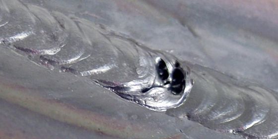
2. Porosity
These defects are caused when hydrogen, nitrogen, and oxygen are absorbed in the molten weld pool. Upon solidification, they are trapped in the weld. Grease, moisture, paint, and rust can also cause porosity.
To prevent this issue, ensure the plate edges are clean and dry, use fresh welding materials, and check the welding torch for leakages.
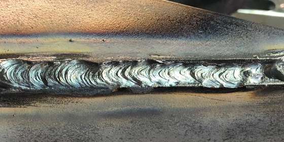
3. Undercut
Undercut occurs when high voltages or long arc lengths are used. Utilizing an incorrect electrode or one that is too large relative to the thickness, as well as a fast travel speed of the torch, can also cause this problem.
Such defects can be averted by using an electrode that is just the right size, ensuring that the torch is moved slowly, and avoiding holding near the vertical plate if a horizontal fillet weld is being made.
4. Cracks
Cracks can form on the weld when the internal stresses are greater than the strength of the weld or base metal (or both). They can propagate over time, and therefore, must be addressed immediately.
These defects can be avoided by carefully cleaning, filing, grinding, and deburring the edges of the metal plates so that they fit together well. Ensuring the temperature is right while reheating both sides of the joint also helps.
Apart from sheet metal forming processes, other common defects can occur during the manufacturing process.
For example, some of the common include surface scratches, contamination, dents, and pinholes. Also, non-uniformity could occur due to high tensile stresses or compressive buckling during the sheet metal fabrication process.
Sometimes, controlling these defects can be difficult, and often requires special attention during the process.