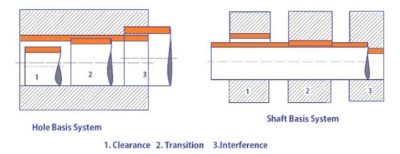
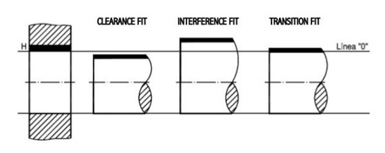
As we briefly mentioned before, there are three main categories of engineering fits. Each one has a different mechanical contact and a different job to perform. In this section, we dive deep into these types of fits and their sub-categories.
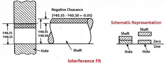
1. Interference Fit
The interference fit is a type of engineering fit where high frictional force tightly holds the mating surfaces together. Consequently, the interference fit is also known as a friction fit.
The tightness of interference fits comes from its negative clearance. This means that the mating surfaces press into each other. In other words, the mating surfaces deform inwards under contact pressure. For instance, in a hole and shaft system, the hole is actually smaller than the shaft in an interference fit. The shaft is forcefully press-fit (another name for interference fit) into the hole via a hydraulic press or hammers.
Additionally, another common method to create interference fits is by shrink-fitting. In this technique, one of the parts is either cooled or heated so that it contracts or expands (respectively) enough for the negative clearance to momentarily change to positive clearance. After locating the parts against each other, the temperatures normalize. The resulting thermal shrinkage/expansion creates a tight interference fit.
Generally, the clearance in an interference fit is -0.001mm to -0.042mm. Now, let’s see the sub-categories of interference fit:
Press Fit: A lighter variant of press fitting with minimal negative clearance for medium-strength joints.
Driving Fit: Medium interference joint that can carry loads and requires cold/hot pressing and force to assemble.
Forced Fit: Forced fits are the strongest type of engineering fit. They require cold/hot pressing and are almost always permanent. Their assembly warrants careful tolerancing and placement to avoid the breakage of parts.
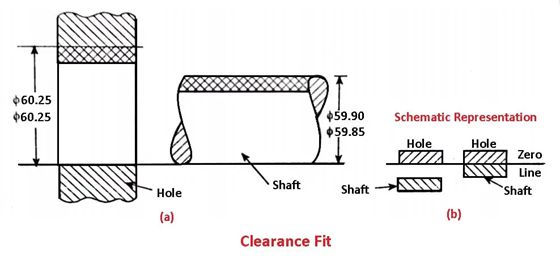
2. Clearance Fit
A clearance fit has a positive allowance. This means that there is a slight gap between the mating surfaces. As a result, the parts also have some play, but it is negligible and often not observable to the naked eye.
Due to this play, parts in a clearance fit have a certain degree of freedom (of movement). For example, the pin and frame in pivot joints have a clearance fit, allowing both components to move independently of each other but also stay locked in place at the same time.
The common range of clearance in these engineering fits is +0.025mm to +0.089mm. A summary of the clearance fit types is as below:
Loose Running: The clearance is set at the higher end of the range given above. Parts in a loose running clearance fit are free to rotate/slide and have an observable play.
Free Running: Similar to a loose running joint. Parts can move at high speeds and the joint can accommodate thermal expansion. However, the location accuracy is low due to considerable play.
Close Running: Close running fits have a slightly better positioning accuracy and allow parts to move even at high temperatures and speeds.
Sliding: Sliding joints are high-accuracy engineering fits. Clearance is kept to a minimum to restrict all degrees of freedom except in the sliding direction.
Location: Location fits are very high-precision fits to locate the mating parts accurately. The clearance is very low and requires lubrication to allow smooth motion.
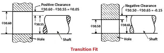
3. Transition Fit
Transition fit is a middle ground between the other two engineering fits. Depending on the application, the mating parts can have either a small interference or clearance.
If there is a negative interference, like an interference fit, the pressure and load-carrying capacity is not that high. If there is a clearance, as with a clearance fit, there is not as much play.
Typically, a transition fit is useful for precision-locating parts in assembly operations. It restricts their relative movements while also preventing extreme mechanical stresses.
The mechanical interference/clearance in transition fit ranges between +0.023mm to -0.018mm. Furthermore, transition fit has two common types:
Similar Fit: A very light engineering fit with near-zero clearance/interference. Generally, a human-applied force with a mallet is sufficient to achieve the fit.
Fixed Fit: Slightly tighter than a similar fit that requires a press to achieve.
The information in the previous section can be too much to absorb in one go. To understand it better, let us zoom out a bit and try to get a bird’s eye view of engineering fits. A great way to do this is to discuss common engineering standards for types of fits.
The two most popular standards regarding engineering fits are ISO 286 and ANSI B4.1. Both standards provide comprehensive information on tolerance ranges for different fit types. One can find reference tables from these standards in every fabrication shop, signifying their importance in the industry.
Since the ISO standard is the more well-known of the two, the following chart focuses on it.
| Type of Fit | Hole Basis | Shaft Basis | Fit Type | Applications |
| Clearance Fit | H11/c11 | C11/h11 | Loose Running Fit | Pivots, parts with corrosion and dust, parts exposed to thermal changes |
| H9/d9 | D9/h9 | Free Running Fit | Cylinder-piston assemblies, slow-rotating parts | |
| H8/f7 | F8/h7 | Close Running Fit | Machine tool spindles, shaft bearings, sliding joints | |
| H7/g6 | G7/h6 | Sliding Fit | Sliding gears, clutch disks, hydraulic pistons | |
| H7/h6 | H7/h6 | Locational Clearance Fit | Machine tool guides, roller guide rails | |
| Transition Fit | H7/k6 | K7/h6 | Locational Transition Fit | Wheels, brake disks, gears/pulleys on shafts |
| H7/n6 | N7/h6 | Locational Transition Fit | Motor armature windings, gears | |
| Interference Fit | H7/p6 | P7/h6 | Locational Interference Fit | Hubs, clutches, bushings for bearings |
| H7/s6 | S7/h6 | Medium Drive Fit | Permanent gear/pulley assemblies, bearing mounting | |
| H7/u6 | U7/h6 | Force Fit | Flange mounting, gears, shafts |
It is clear from the above discussion that dimensional tolerance is a critical factor for accurate engineering fits. However, manufacturing the mating parts within the required dimensional tolerances is a skillful task.
Generally, the tolerance limits are included in engineering drawings via appropriate GD&T symbols. GD&T sets acceptable limits on the amount and nature of geometric deviations from the true geometry. Thus, the fabricator must manufacture the parts within these set limits.
There are numerous techniques manufacturers may utilize to achieve this. These include:
CNC Precision Machining: CNC machines have remarkable accuracies up to +/- 0.001mm. Using the correct tooling and fixturing, machinists can produce accurate parts for engineering fits.
Grinding: Grinding is the go-to method for ultra-precise manufacturing owing to its impressive manufacturing accuracy of +/- 0.25 microns. For critical applications like a forced interference fit, tolerances of this order are common.
Reaming: It is a specialized application for hole-making. Since holes are a very common mating component in engineering fits, reaming is worth a mention in this list. Since it is a precise method that removes a minuscule amount of material, it is useful in bringing holes within the tight dimensional tolerances required for mechanical fits.