The parameters of gear are simply technical properties of the gears. These parameters apply to different gear parts, and industry engineers need to pay attention to them.

Number of Teeth: Teeth are the jagged faces outside of the circumference of the gear. With teeth, there can only be a whole number as the number of teeth. Also, the number of teeth on the gear determines the gear ratio, which is an influential factor in how the gear behaves.
Whole Depth: This is the distance between the outermost part of the tooth to the lower part of the tooth.
Pitch Circle: Gears are generally circular, and the pitch circle is the parameter that implies the size of the gear. To form a mesh, intermeshing gears must have tangential pitch circles. This parameter is the most important of all other circumference-related gear parameters, and all others are defined according to the pitch circle. In addition, the pitch circle splits the gear tooth into the addendum and dedendum, the upper and lower part of the tooth, respectively.
Root Circle: This is the gear’s inner diameter, which is important in demarcating the lower part of the tooth.
Outside Circle: This is the gear’s external diameter, and it demarcates the upper part of the tooth.
Pitch Diameter: This is simply the diameter of the gear and is obtained by measuring the diameter of the pitch circle. The pitch diameter is important in estimating the optimal distance between two gears.
Circular Pitch: This is the distance between two adjacent teeth in a gear. It is obtained by marking one part on a tooth, and marking the same part on the following tooth, then measuring the distance between these two parts. The circular pitch offers valuable information about the number of teeth in the gear.
Module: This parameter is related to the circular pitch and is obtained by dividing the circular pitch value by 3.142 (pi). The gear module is often preferred during analysis over the circular pitch.
Diametral Pitch: This parameter relates the diameter of the pitch circle to the number of teeth on the gear. The diametral pitch is important in determining if two gears will intermesh, as only gears with the same value for this parameter will intermesh.
Circular Thickness: In simple terms, this is a measure of how thick an individual tooth of the gear is.
What you see when you use a mechanical gear is two gears meshing their teeth followed by the transference of speed and motion. But what happens behind the scenes?

To start with, know that the gears are attached to components called shafts. Rotation of the gears occurs along the shaft. The two gears involved in an intermeshing are the driving and driven gear. The driving gear is responsible for the initial rotation, while the driven gear represents the gear that gives the final rotation due to the effects of the driving gear. Any rotation of the driving gear is met with rotation of the driven gear.
For all gears, there is a transfer of motion between the driving and driven gears. However, for some gears, the motion transfer can change the direction of rotation, while for other gears, it can lead to movement. The determining factor for whether there is rotation or movement change is the design of the two gears.
For machines that want the gear intermeshing to impact speed and torque, the gear pair can be designed to be of different sizes.
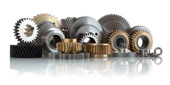
Depending on their properties and design characteristics, there are different types of gear. Aside from understanding how gears work, it is essential for machining engineers to understand the different types and their peculiarities for the best possible results. These gears are outlined below.
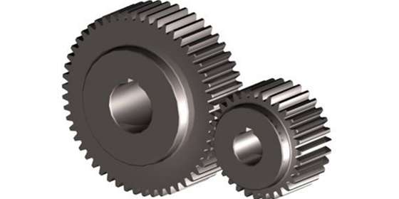
1. Spur Gear
Sporting a simple design, spur gears are the commonest types of gears in machines today. Spur gears belong to the class of gears where the tooth is parallel to the shaft. Considering that these gears have a parallel design, the efficiency of transmission of both motion and power is usually high.
One distinct feature of spur gears is that they do not transmit load in the axial direction. Also, the way spur gears are set up makes them the optimal gear for processes that do not require a high speed.
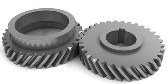
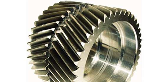
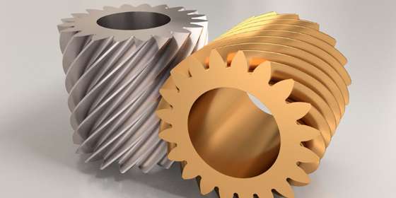
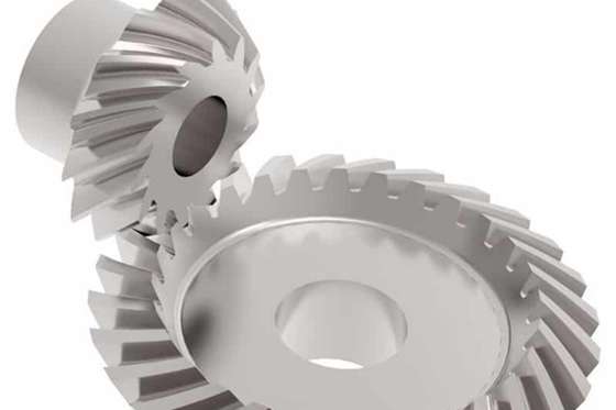
2. Helical Gear
Helical gears are so named because of their helix shape, similar to helical springs. Like spur gears, helical gears are commonly used across manufacturing industries and machines.
However, unlike spur gears with teeth positioned parallel to the shaft, helical gears have their teeth set at an angle to the shaft. Also, more teeth are involved when transmitting motion and speed, which translates to helical gears having the ability to carry more load.
Again, helical gears transmit load in the axial direction, creating a thrust force and needing bearings. Helical gears are perfect for operations that require high speed. There are different variations of helical gears, and they are as follows:
2.1 Single or Double Helical Gear
Depending on whether the gears have teeth on one or both helixes, helical gears can be subdivided into two. If teeth are only on one helix, the gears are single helical. The hand (left or right) the teeth are on does not matter as long as only one side contains the teeth.
However, the gears are known as double helical if there are teeth on both hands. There is a gap between the two faces in a double helical gear. Of the two subtypes, the double helical gears are the more efficient and smother in transferring motion because there is more overlap of the teeth.
2.2 Screw Gear
Screw gears are a pair of helical gears with the same hand and operate at a twist angle of 45 degrees. They have a similar design to many fasteners. These gears usually operate on gears that are neither parallel nor intersecting. Unlike conventional helical gears, screw gears only have one tooth as the point of contact, which affect their ability to carry high power and loads.
3. Herringbone Gear
This type of helical gear is similar to double helical gears, with the difference being that the Herringbone gear is shorter, and there is no space between the two faces. While Herringbone gears are suitable for operations that involve a lot of vibration and shock, they are expensive and difficult to manufacture, implying that they are not widely used in industries.
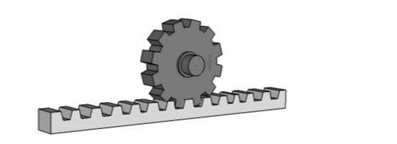
4. Rack Gear
This gear type has similarly-sized teeth equidistance to one another along a linear rod called the rack. Also, the gear rack has a pair of circular gears known as the pinion that engages the rack. The mesh between the pinion and the rack turns rotational into linear motion. This type of gear is mostly used in the automobile industry for the manufacture of steering.
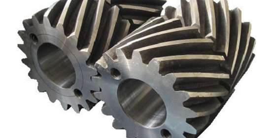
5. Bevel Gear
A bevel gear is a cone-shaped gear with teeth around the cone that is used for the transmission of force between intersecting shafts. The shafts can intersect perpendicularly or at a specific angle. This gear type is not widely used in the industry because it is relatively expensive. Still, the gear is used in the manufacture of mixers and crushers.
There are several types of bevel gears, and they are highlighted below:
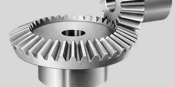
5.1 Straight Bevel Gears
This subtype of bevel gears is the most typical in many industries, primarily due to their simple setup. While the gear’s pitch is conical, the teeth are upright.
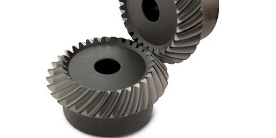
5.2 Spiral Bevel Gear
This subtype of bevel gears has a curvature in their tooth line, which corresponds to excellent contact points between the teeth of the gear. The result is stronger gear with a smoother transmission. However, they are very expensive.
5.3 Miter Gear
If a bevel gear has a gear ratio of one, it is referred to as a miter gear. This is an important feature to note, considering other gears of this type can have up to a 400:1 ratio. Miter gears are the best bevel gears for operations requiring efficient transmission at high speeds.
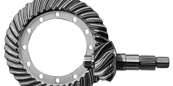
5.4 Hypoid Gear
There is a striking similarity between spiral bevel gears and hypoid bevel gears, with the primary difference being whether or not the shaft intersects. If they do, the bevel gear is known as spiral, but if they don’t, the gear is hypoid.
Other types of bevel gears include:
- Helical bevel gears
- Angular bevel gears
- Crown gears
- Zerol bevel gears
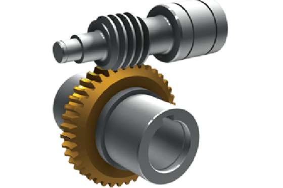
6. Worm Gear
This type of gear comprises two important components: the worm and the worm wheel, which are simply the shaft and mating gear. The shafts in this gear have a screw cut, like a drill, and do not intersect.
Transmission generally occurs very smoothly and quietly because there is limited friction between the hard worm and the soft worm wheel. However, this type of gear is not the most efficient. Worm gears are mostly used in agricultural machines.
7. Internal Gear
For this gear type, there are teeth on the inside cones. For transmission of motion, there is an external gear paired with the internal gear, with both gears rotating in the same direction. Because the number of teeth on the internal and external gears often differs, several problems may arise when using this type of gear. Nonetheless, the gear is useful in shaft couplings.
There are several types of gear belonging to different classes. Choosing the right gear is critical to the success of the operation. However, knowing which gear is right may be tricky because of the variety of gear available. Fortunately, there are a few considerations and tips that can help in the choice of the right gear. They include:
1. Budget
All manufacturing companies want the best and most efficient machines to handle their operations. Sometimes, this may result in the customization of gears using engineer drawings and recommendations just to meet their needs.
Unfortunately, this customization does not come cheaply. Aside from customization, some gears are very expensive and do not have easy manufacturing. It is critical to consider the budget before choosing a gear for manufacture.
2. Design Standards
There is no one-size-fits-all standard when designing and manufacturing gear. Instead, there are different specifications, standards, and engineering tolerances by which gears can be manufactured. For companies that need the gear, it is important to consider the particular standards of the gear.
If such companies cannot get a specification that fits the bill of what they need, they may have to move to another region to get the right gear. The different regions with different standards are the United States, Japan, and Germany.
3. Space Restrictions
The availability of space in the gear design is an important factor that determines the choice of gear for a manufacturer. Generally, gears are situated in the center of shafts. But, in some instances, the manufacturing needs may require the gears to be farther away from the center. If this is the case, the gear must undergo some other changes to maintain effectiveness and efficiency. One such change is an adjustment of the tooth profile and thickness.
Alternatively, manufacturers may go for gears that better manage space. The most common gear turned to for this is the internal gear.
4. Transmission Needs
Mechanical gears typically deal with motion and torque transmission between the various parts of a machine. Different machines have different transmission requirements and needs. For some machines, only a change in movement is required; for some, only a change in torque is required; while some machines need a change in movement and torque.
Depending on what the manufacturer requires for their operation, a suitable gear can be chosen, and the type and design of the gear are subsequently adjusted.
5. Service Conditions
The conditions under which the mechanical gears work can affect how well they perform and how long they last. The service conditions can be divided into operational and environmental conditions. For the former, the considerations important are the – weight on the gear, the friction, noise, vibration, and stress are important considerations.
On the other hand, the environmental conditions include the following considerations – temperature, cleanliness, and humidity. Therefore, the environmental and operational conditions affect the gear construction material, surface treatments, and lubricants used.