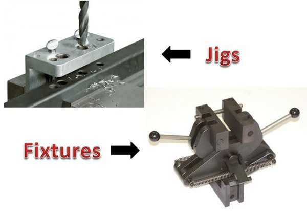
Difference Between Jigs and Fixtures & Their Design Consideration

Custom-CNC -machining -feature image

What is the difference between jig and fixture? It is common to see them together. However, they are not interchangeable despite their comparable purposes. Examining how they are utilized to enhance manufacturing quality, cut production costs, and automate work will help us better understand the subtle variations between various manufacturing technologies.

Innovative manufacturing concepts such as Lean Production System, Cellular Manufacturing, Single Minute Exchange of Dies, and Takt Time Analysis have been introduced into the production process. For these innovative approaches, a slew of effective, low-cost instruments and work holding devices is required. Read on to learn more about the difference between jig and fixture.

What is a jig?

jig

Jig are tools used to hold and locate the workpiece during the production process, as well as to guide the cutting tools.

In other words, a jig holds the workpiece and guides the tool to increase reproducibility, precision, and productivity of manufactured parts.

A drill jig is a common example of a jig. They guide the drill as it makes holes in desired locations. Utilizing drill jigs significantly boosts the manufacturing pace.

Types of Jigs

Below are the types of jigs.

1. Template jig

Template jig

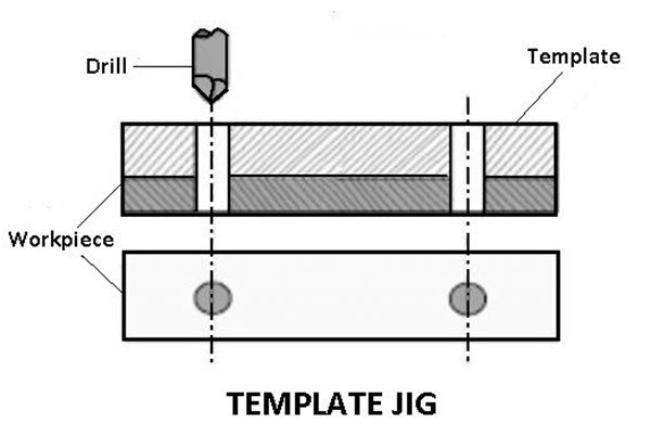
The simplest model is the template jig. The plate, which has two holes, serves as a template for the part to be machined and is attached to it. The template’s holes are used as a guide for the drill, and the holes on the workpiece are drilled at the same relative positions as the ones on the template.

2. Plate jig

Plate jig

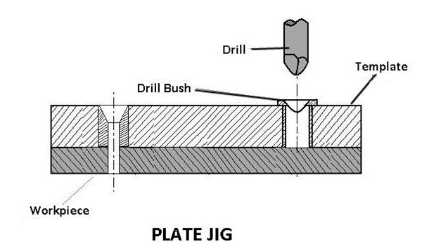
Angle plate jig is used to improve the template jig, drill holes are added to the template’s surface. With the plate jig, precise hole spacing may be maintained when drilling massive components.

3. Channel jig

Channel jig

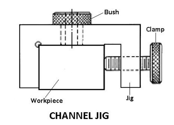
A channel jig has a cross-section that resembles a channel. Rotating the knurled knob locates and clamps the component inside the channel. The drill bush serves as a guide for the instrument.

4. Diameter jig

Diameter jig

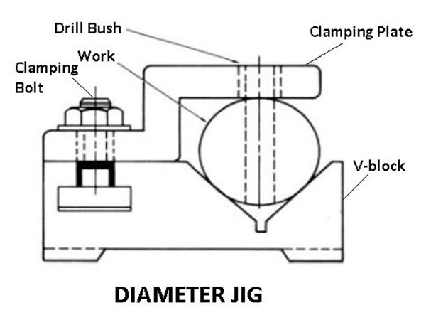
Drilling radial holes on a cylindrical or spherical workpiece can be done with a diameter jig.

5. Leaf jig

Leaf jig

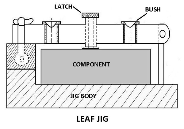
Loading and unloading can be accomplished with the use of a leaf on the jig.

6. Ring jig

Ring jig

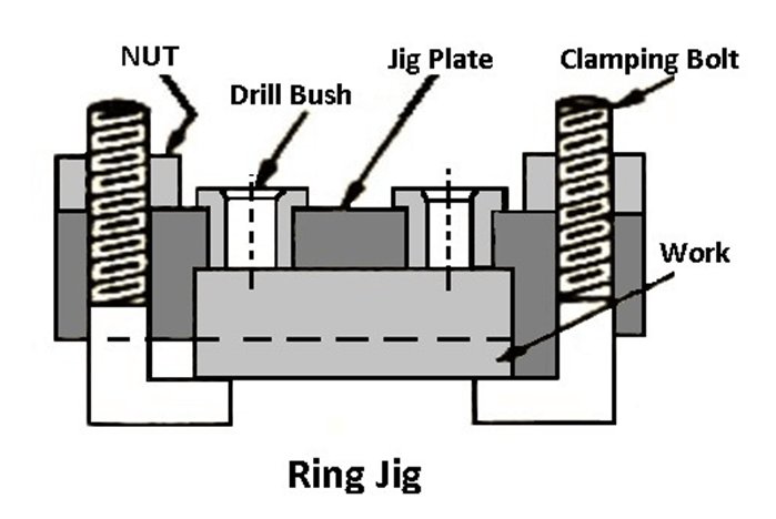
To drill holes in circular flanged items, a ring jig is used Holes are drilled by guiding the tool through drill bushes while the work is securely attached to the drill body.
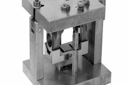
7. Box jig

Box jig

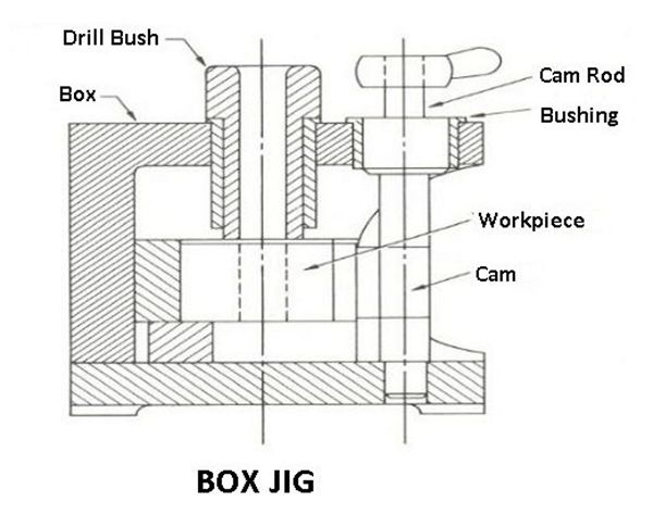
This type of jig has a box-like design within which the item is held tightly so that it can be drilled or machined from a variety of angles at the same time.

What is a fixture?

Fixtures are used in manufacturing tools that allow for automation in the production process. When it comes to automated industrial processes, you’d be hard-pressed to find one without fixtures. Fixtures that hold and guide automobiles during the welding and assembly process.

For example, It is necessary for an automobile assembly line. To check the quality of the manufacturing processes, they can also be employed to hold a product in place while an optical or laser scan examines it. It’s almost impossible to walk through a production facility without encountering some sort of fixture.

Types of fixtures

1. Turning fixture

Turning fixture

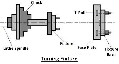
Lathes have a typical job holding devices like chucks and collectors, between the center and on mandrels or faceplates, making it easy to hold the regular workpieces. However, holding oddly shaped components can be a challenge.

In a four-jaw chuck or employing shaped soft jaws, simple odd-shaped projects can also be retained in chucks. In contrast, workpieces with complex shapes must be kept in place with the aid of turning fixtures. Workpieces are secured in place by these fixtures, which are typically fixed on the spindle’s nose or a faceplate.

2. Milling fixture

Milling fixture

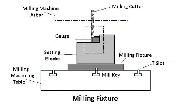
Workpieces are held in place by milling fixtures, which are commonly fixed on the spindle’s nose or a faceplate. The table is shifted and positioned in relation to the cutter in order to achieve the desired results. Before beginning the process, the workpieces are placed in the fixture’s base and clamped.

3. Broaching fixture

Broaching fixture

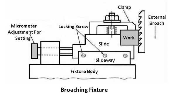
To locate, hold, and support workpieces during operations like keyway broaching and hole broaching, these fixtures are utilized on a variety of different types of broaching machines Broaching internal pull-type holes with a clamping plate as a fixture.

4. Grinding fixture

Grinding machines employ a variety of fixtures to locate, hold, and support workpieces while they are being ground. Work-holding devices such as chucks, mandrels, and the like can be used in conjunction with these fixtures.

5. Boring fixture

The construction of this fixture does not need to be as robust as milling fixtures because it will never be subjected to the same heavy cutting loads that milling fixtures are exposed to.
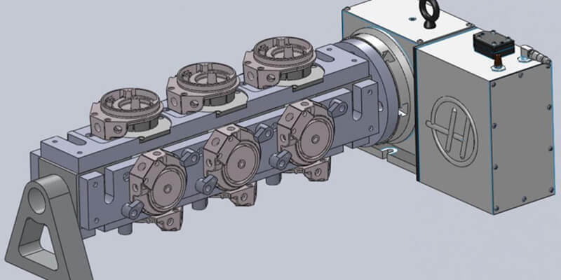
6. Indexing fixture

Indexing fixture

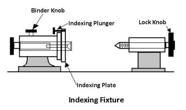
Several components must be machined on various surfaces in order for their machined surfaces or shapes to be uniformly spaced. In order to manufacture as many surfaces as possible, these elements must be indexed a corresponding number of times. A suitable indexing mechanism is built within the holding devices (jigs or fixtures). An indexing fixture is a fixture that includes a device that can be used to index data.

7. Tapping fixture

For cutting internal threads in drilled holes, tapping fixtures are designed to hold and stabilize identical work components. Unevenly shaped and imbalanced parts will always necessitate the employment of specific fixtures, especially when mass-produced tapping is required.

8. Duplex fixture

A fixture holding two identical components at the same time and allowing them to be machined simultaneously at two different stations is known as the duplex fixture.

9. Welding fixture

Fixtures for welding are meant to keep welded structures from distorting throughout the process since they hold and support the various components. Clamping must be light but firm, and clamping parts must be placed far enough away from the welding area for this to work. To survive the forces of welding, the fixture must be extremely solid and rigid.

10. Assembly fixture

The purpose of these fittings is to hold the various parts of the assembly in their correct relative positions.

Jigs vs. Fixtures: What's the Difference?

Jigs vs. Fixtures

Jig vs fixture, what is the difference? There are two main instruments used in mass production processes: jigs and fixtures. It’s common for people to mistakenly use the two names as synonyms, yet they actually perform separate functions.

Jigs guide the cutting tool to a certain spot on the workpiece that has been predetermined. A workpiece is supported and located with the use of fixtures. Unlike a jig, fixtures do not hold the tool in place on a workpiece.

When compared to fixtures, jigs are more compact and require less weight to be stable when subjected to high cutting and vibrational pressures. In contrast to fixtures, jigs can be held or attached to a table depending on the task at hand and require no additional tools.

Why Are Jigs And Fixtures Important In CNC Machining?

Careful selection of jigs and fixtures will significantly improve the economy of the fabrication process by allowing smooth operation, simplified production, and quick process transition. Jigs and fixtures help compensate for the constraints of the CNC machine in working with a part. They are designed to provide secure mounting and maintain the part location’s reliability during the machining process. Described below are the different roles of tooling and fixturing for custom CNC machining:

1. Part Holding

One primary purpose of jigs and fixtures is to provide secure mounting of the part during the machining process. They are custom-designed to fit the particular part being machined. They provide custom part holding whenever a part may need to be held at a specific angle or to be clamped at a particular shape.

Reliable custom fixturing is crucial in preventing undesired inaccuracies caused by chatter and tool pull out. Some examples of fixtures used as part holding are vises, chuck, centers, milling fixtures, and various holding plates.

2. Parts Protection

One role of jigs and fixtures is they protect the work part while machining. They are a great help for maintaining the desired surface finish and maintaining proper runout.

Sleeve, bushing, and masking fixtures are commonly designed for custom parts where the surface finish is controlled. This is done to protect the surface of the finished part from the metal chips/ swarf from different machining processes for the work part. Furthermore, customized machining centers are specifically designed to cater to custom parts with tight callouts on overall runout.

3. Location Control/ Fool Proofing

Jigs and Fixtures are very essential in maintaining dimensional and location accuracy. They hold the workpiece at the right location and orientation during the machining process. For these reasons, it makes fixtures a convenient way of incorporating foolproofing in a process to minimize errors due to human factors.

Fixtures control the location, orientation, and stability by constraining the degrees of freedom in the work part. This is done by using pins, clamps, planes, and fasteners in designing the needed fixture. Planes provide support for the part, clamps allow adjustable mounting while having the accessibility of being dismounted, and pins provide precise location control for specific features.

In custom parts machining, features like holes and slots are controlled at a specific location where it could be hard to machine because of some mounting constraints, and that is why fixtures are designed. Fixtures are the most reliable way of machining difficult part features.

4. Part Consistency

Fixtures make it possible to machine multiple custom parts while maintaining their quality. They make sure the quality is consistent from part to part. Examples of the feature controls that need consistency are flatness, parallelism, perpendicularity.

5. Set up Reduction

Fixtures are a great way of eliminating the tedious process of inspecting while loading a part. A fixture designed for a specific part makes the whole CNC process a plug and play operation. The operator’s work will be just to load the work partly because all the necessary location control and parts referencing are already managed within the fixture. Many CNC machining fabricators are doing this in their process to save precious setup time for other value-adding processes. Some examples of fixtures that lessen set up time are the SMED (single minute exchange of die) Fixtures, Milling Fixtures, soft jaws, hex milling fixtures, and many more.

Basic methods and steps to make jigs and fixtures

Pre-design preparation of jig and fixture design original information including the following.

(1) Design notice, finished parts diagram, blank diagram and process route and other technical information.

Understanding the processing technology requirements of each process, positioning and clamping program, the processing content of the previous process, the blank situation, the machine lathe used in processing, tools, inspection gauges, machining allowance and cutting amount, etc.

(2) Understand the production batch and the need for jigs and fixtures. Roughly determine the number of jigs and fixtures needed.

(3) Understand the main technical parameters of the machine lathe used, performance, specifications, accuracy and the jig connection part of the structure of the contact size, etc.

(4) The material stock of the jig and fixture. The following materials are used to make jigs and fixtures: hardened steel, grey cast iron, plastic, carbide, epoxy resins, stainless steel, bronze, low melt alloy steel. You can select the right material according to the processing project.

The design consideration of jigs and fixtures

Jig and fixture design generally have a single structure, giving the impression that the structure is not very complex, especially now that the hydraulic fixture is in vogue, making its original mechanical structure greatly simplified, but if the design process is not considered in detail will inevitably lead to unnecessary trouble. Therefore, the following points need to be considered when designing jigs and fixtures.

(1) The blank allowance of the machined part. If the blank size is too large, it will result in interference. So be sure to prepare a blank drawing before design. Leave enough space.

(2) The chip evacuation of the fixture is smooth. Due to the limited processing space of the machine tool, jigs and fixtures are often designed to be more compact space, which is often ignored in the process of machining generated chips in the fixture dead-end storage.

Another problem is that it may lead to the chip fluid outflow is not smooth, bringing a lot of trouble to the future processing. So at the beginning of the actual process should consider the problems that arise in the machining process. After all, the jig and fixture are to improve efficiency and facilitate operation.

(3) The overall openness of the jig and fixture. Neglecting the openness will cause the operator to have difficulty in loading the card, which is time-consuming and laborious.

(4) The basic theoretical principle of jig and fixture design. Each set of jig and fixture has to go through countless clamping and unclamping actions, so it may be able to meet the user’s requirements at the beginning.

The jig and fixture should have accuracy retention, so don’t design something that goes against the principle. Even if you can get away with it at the moment, it will not be sustainable in the long run. A good design should stand up to the hammering of time.

(5) The replaceability of the positioning elements. Positioning elements are severely worn. So it should be considered for quick and easy replacement. It is best not to design for larger parts.

Hi,click here to send us a message.