Let us begin by establishing a datum definition. ASME Y14.5 (1994) defines a datum as “A theoretically exact point, axis, or plane derived from the true geometric counterpart of a specified datum feature. A datum is an origin from which the location or geometric characteristics of features of a part are established.”
In easy words, a datum serves as a reference entity for measuring and locating the different geometric features of a part.
Moreover, an additional piece of information is regarding its usage with other GD&T symbols. The datum symbol is compatible with all GD&T symbols except for those related to form tolerances (flatness, straightness, for example).
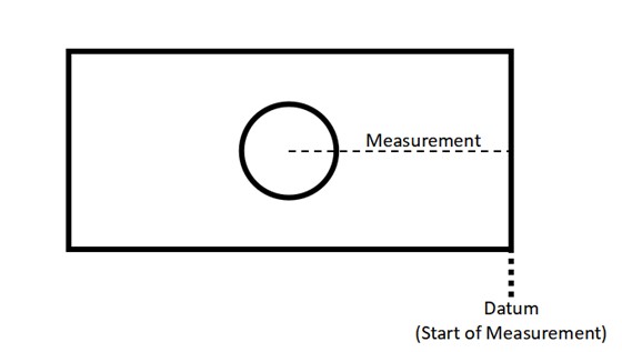
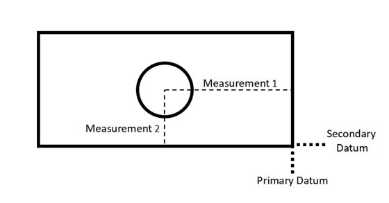
To further drive the point home, consider this very easy example. Suppose you drew a rectangle with a hole at its center. Now, you want to check how off-center you drew the circle. For this, you will have to measure the distance between the edge of the rectangle and the center of the circle. In this case, your datum will be the edge of the rectangle as that is the reference line you start measuring from.
Now, we can move on to more nuanced topics that will help you better understand the datum definition above.
Datum vs. Datum Feature
Confusing the terms ‘datum’ and ‘datum feature’ is a common mistake. One must be clear about both to make professional engineering drawings.
A datum feature is a physical, tangible feature of the part that establishes the datum. Since it is a real entity, it is not exact and can have an irregular form.
The datum is a relatively more abstract concept. It is a geometrically exact representation of the datum feature. So, for example, if a rough surface is the datum feature, the datum will be the perfectly smooth plane that best simulates the surface.
Datum Reference Frame
The datum reference frame (DRF) is a GD&T term that refers to the coordinate system that locks the part’s degrees of freedom during inspection and measurement. By ‘locking’, it means that it orients and locates the part in space and provides a base system for all tolerance zones. The DRF provides a reference system to measure the part’s features.
Since there are six degrees of freedom for any feature, the DRF should lock all of these. This is typically done with three planes, which are easy to simulate in a physical environment as well.
The figure below presents an example. There are multiple features to measure in the part. First, imagine you want to inspect the part without the blue component. It will be difficult and unreliable as you do not have proper references to measure with. The three blue planes form the DRF that orients and locate the part.
Primary and Secondary Datums
In the GD&T datum system, a single datum is generally not enough to completely measure a part. Thus, engineering professionals use multiple types of datums for the comprehensive dimensioning of parts.
The datums, however, are set according to priority. The primary datum is the most crucial to the form and dimensions of the part while the secondary datum comes after it. In many cases, designers also define a tertiary datum.
Let us go back to our previous example and update it. You may have realized that one measurement is not enough to fully locate the center of the circle. Thus, a secondary datum definition is used for the second measurement in the vertical direction. This completes the measurement.
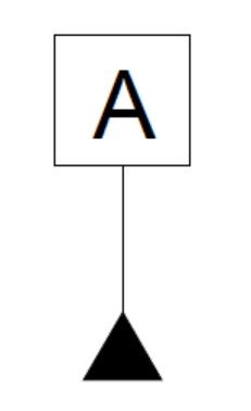
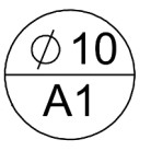
Datum targets are a key concept in engineering drawing and dimensioning. The datum target symbol, shown below, is called on datum features for practical reasons like measuring and inspection. In this section, we answer the question of what is datum target.
Datum vs. Datum Target
The datum definition is clear from the text above. It is an exact geometric entity that serves as a reference during measurements and quality inspection.
The datum target is a point, line, or area that serves as an additional piece of information that allows engineering professionals to use the datum feature as a reference for measurement. It is a ‘target’ for establishing physical contact between the part and the measurement device, which is essential to perform measurements.
How to Use Datum Targets?
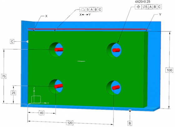
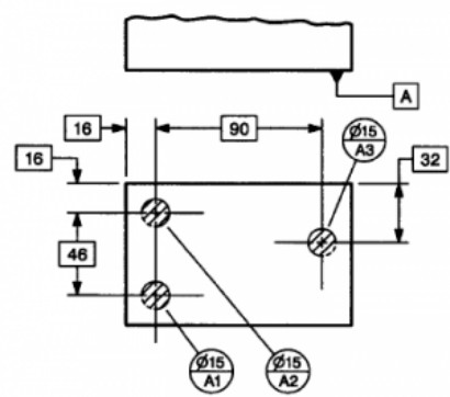
The figure below shows the use of datums and datum targets. The datum symbol establishes the surface on the front as datum A. The datum target symbol is called thrice, each one establishing a 15mm diameter circular contact zone on datum A.
Now, suppose this part goes to a quality inspector who is using a CMM to perform all measurements with respect to datum A. In order to perform these measurements, the inspector must place the datum A surface on the CMM’s worktable.
The datum targets, in this case, are a guide to the inspector about how many mounting pins to use. Additionally, they convey to him where exactly to install these pins. The pins must touch the part within the three target zones for the datum to be established according to specification.
The datum symbol is a core concept in the GD&T system. Since every dimension requires a datum, there are numerous ways to call the datum symbol. Thus, it is feasible to divide this according to these applications, which comprise two broad categories.
Datum Symbol on a Surface or Axis
The first method is to declare a surface or axis as a datum. This is arguably the more common usage of the GD&T datum. It means that a planar surface or the axis of a round feature serves as the reference datum for dimensioning.
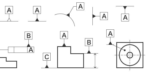
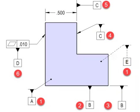
There are several ways of declaring a surface or axis as the datum on an engineering drawing. In the example below, datums A and E are the front and back surfaces, respectively. The solid and dotted line conveys the difference between the front and back sides.
The figure also shows the variations in assigning datums. For example, datum C can be established both by an arrowhead pointing to the surface or by referencing the extension line drawn for dimensioning.
Datum Symbol on a Feature of Size
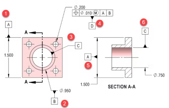
The other case is declaring a feature of size as a datum. A feature of size is a geometric feature with a dimension. For example, bores and slots are features of size.
For example, in the figure below, datum A is referencing the feature with a size of 1.500. Notice that the datum symbol in-line with the dimension arrow, which makes it different from the example above. Datum C is the axis of the 0.750 holes. If the hole’s center is off-dimension, the datum shifts along with it.
These types of datums are generally useful for controlling engineering fits and problems like runouts.