- November 11, 2022
An ejector pin is an ejector system that pushes the molded part out of the mold cavity after injection. Alongside ejector systems such as ejector blades and blocks, ejector allows efficient parts removal after molding.
There are several types of ejector pins. Choosing the right one is challenging due to its effects on the molded part’s functionality and certain aesthetical properties. This article embarks on an ejector definition, its function and defects. Read on more!
What is Ejector Pins Injection Molding?
Ejector pin injection molding is an ejector system mechanism that orchestrates the removal of cooled/molded parts from a die mold cavity. As a result, it helps in increasing the efficiency of the injection molding process.
Understanding the mechanism is possible for the two sides of the mold (Side A and B) as each has a specific role in completing a cycle in the injection molding system. Side A is movable, while Side B contains the ejector system. On cooling, the mold cavity opens and separates, and the ejector pin pushes the now-hardened plastic out of the mold.
Note: During the ejection process, there is a dent on the molded part due to the force of ejection
Types Of Ejector Pins Used During Injection Molding
There are several types of ejector pin systems suitable for injection molding. As a part manufacturer, below are a few you need to consider during rapid tooling:

Ejector Pin #1: Through-Hard Ejector
Through-hard ejector pins require heat treatment to allow the diameter of the pin to withstand high temperatures. As a result, they are appropriate for working with plastic systems under 200⁰C.

Ejector Pin #2: Nitride H13 Ejector
Nitride H13 Pins or case-hardened ejector pins can withstand a temperature of up to 600⁰ C. They can be drilled or tapped, but they are also relatively soft and may chip easily in comparison to other types of ejector pins.

Ejector Pin #3: Black Ejector
Black ejector pins replaced nitride H13 pins as the nitride H13 pins could not withstand temperatures above 600⁰ C. As a result, the pins can resist high heat. They were manufactured with a special self-lubricant to withstand a temperature of 1000⁰ C and are suitable for working with automotive parts. However, they are expensive but meet the required conditions to resist high temperatures.
Other Types of Ejection Systems
The previously discussed pins are the most common in part injection molding. However, there are also other ejector systems that might not be known but are helpful.
–Ejector Sleeves are hollow pins that consist of a hard-surface sleeve pin. The pin has a hole that functions to protect and guide the pin and a fitting core pin
–Ejector Plates function together with the ejector pins by holding the pin head to prevent them from coming out during the molding
–Ejector Blocks have lubricating hollow grooves and are applied on thin products to reduce ejector pin marks. As a result, they are suitable for products that need a high surface finish.
How Does an Ejector Pin Work?
Knowing how an ejection pin works can help select the right machine and prevent ejection pin marks and other defects. To better understand the process, we would divide the injection molding process into three phases: injection, cooling, and part release.
• The injection phase is when the operator introduces molten plastic into the die mold cavity.
• The cooling phase allows the molten plastic to solidify into a hardened plastic.
• After cooling, the part release phase involves using a dedicated mechanism known as an ejector system to remove the molded part from the die mold cavity. There are two general methods: manual and automatic.
On the one hand, the manual part release mechanism is time-consuming and inefficient. It can result in a non-functional/aesthetically displeasing product if the release is not done correctly.
On the other hand, automatic ejector pins and other ejector systems are faster and more efficient. They exert force on the finished parts, pushing them out in one axial motion. The part does not fall freely as the clamp plates and ejector box guide it.
A summary of how the ejection pin system work is described below:
- After the molten part cools down, the retainer moves out of the way;
- The mold push back towards the pins;
- The pins fit into bores of the mold half;
- Then the pins push the molded part to eject it.
Causes and Solutions of Ejector Pin Marks
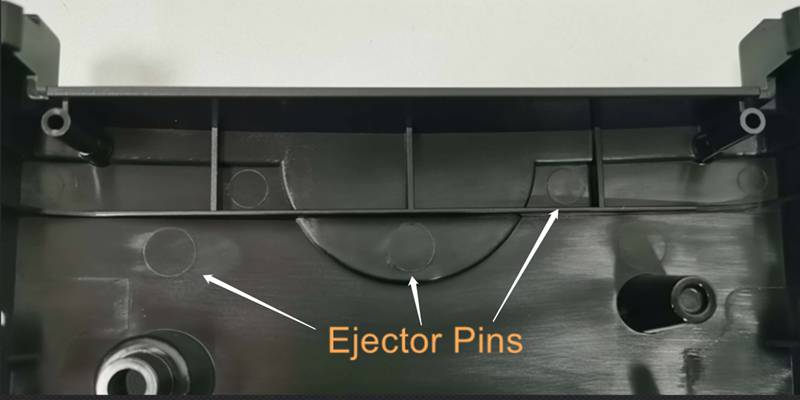
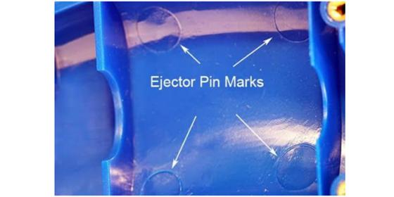
During the ejection process, the ejector pin form an imprint (also known as the ejector pin mark) on the molded part. This means they are necessary. However, they can escalate under certain situations and have detrimental functional and aesthetical effects. Here are the common causes of ejector pin marks and the corresponding solutions.
Less Cooling Time
If the molded part does not cool before the ejection process starts, it can lead to the penetration of the pin into the part. As a result, this can be disastrous functionally and aesthetically. To solve this, you must ensure enough cooling time to solidify the molded part properly.
Thin Product and Other Characteristics
The part design will also determine whether there will be ejector pin marks. These marks will be more prominent on very thin parts. As a result, there is a general acceptance that the injection molded product should have at least a wall thickness of 2.5mm. Also, plastic that requires a good surface finish should not use an ejector pin. Instead, they should use other ejector systems, such as the ejector blade.
Dwell time and Dwell Temperature
A high dwell time can also increase the chances of ejection pin marking occurring. Dwell time is the time the plastic spends in the mold, while dwell temperature is the Temperature maintained in the mold. Generally, the dwell temperature is higher than the glass transition temperature (the temperature where an amorphous polymer develops glass-like attributes).
Dwell time can increase the glass transition temperature, which could lead to premature ejection. Premature ejection means the product is likely not hard, which could lead to ejector pin marks. You can avoid this by reducing the dwell time.
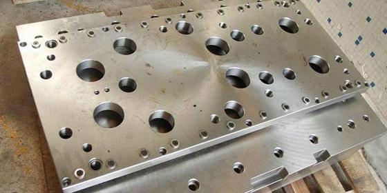
Ejector Pin Placement and Arrangement
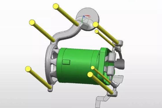
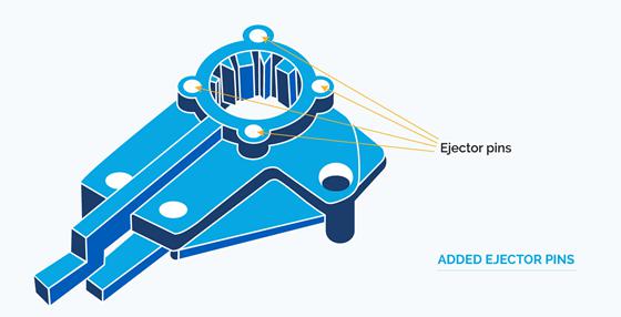
The placement of the ejector pin can also result in pin marks. However, placing them depends on the molded part complexity and mold design. Below are a few placement tips you can use:
- The more complex the part, the more the number of ejector pins needed.
- Place the ejector pin in parts such as the steps, metal insert, pillars, and thick parts.
- Always place the ejector pin on a flat surface, as placing them on steps or slopes will reduce their ability to support the molded parts’ stress.
- Consider the spacing between the pin and the cooling channel not to disrupt the cooling process.
- Place the pin where the ejection force is large, e.g., the core and rib.
Types of Machine
Also, choosing the right injection molding machine can help reduce the markings on the molded part. For example, large-capacity machines are unsuitable for working with small molds in low-volume injection molding due to the internal stress caused by increased pressure.
Holding pressure
Ejector pin markings can reduce by modifying the holding pressure, i.e., the pressure that keeps the molten plastic in place while it cools.
Note: The greater the pressure, the more challenging it is to remove the product.
Other Methods of Reducing Ejection Pin Marks
- Use abrasion-resistant plastics such as nylon, polyoxyethylene, and ultrahigh molecular as they can resist the marks.
- Using a mold release agent for an easier and smoother ejection process.
- Incorporate a draft angle to reduce the part release process and the work done by the ejector pin.
How To Choose the Right Ejector Pins In Injection Molding?
To choose the right pins, you must consider the materials, size, etc. Below is an explanation of these factors and others you might need to keep an eye on during the injection molding cycle.
Choose a Large Ejector Pin Diameter
Generally, it would be best if you used a large ejector pin for a large molded part because a large diameter will reduce the penetration of the pin into the molded part by reducing the penetration force. Furthermore, you should ensure the diameter is an integer (avoid decimals and non-standard values.
Ejector Pin Size
Although the pins should have a large diameter, they should also have a corresponding small size. Adjusting should depend on the size of the molded part. Reducing the ejector pin size will reduce the penetration into the molded part.
Strength Requirement
The pin should be strong enough to withstand the high injection pressure. You can avoid bending the pin by ensuring the diameter is equal to or greater than 2.5mm. If not, you should use a shoulder ejector pin. Also, you should ensure the strength could counter the undercut in injection molding.
Other factors include the type of materials. Also, it would be best if you considered the price of the ejector system, especially for replacement during maintenance, as the price of the ejection system could drive the mold cost.
Conclusion
The ejector pins enable the removal of a molded part from the die mold cavity. There are several types of pins and considerations when working with one. As a result, selecting the right one can be very challenging. This article discussed the ejector pin system and other considerations associated with using the system in injection molding.
Are you looking for rapid tooling and injection molding services? Contact WayKen and get quality mold parts delivered in a short lead time and competitive price.
FAQs
What is a pin mark?
Ejector pin marks, also known as pin push, are shiny or white stamps. These marks are left by an ejector pin and are visible on the component’s class-A surface. Ejector pin markings should be avoided since they are susceptible to cracking.
How do spot ejector pin marks?
Finding ejector pin marks more quickly when you know where the pins are is easier. Ejector pin markings appear on a molded item as glossy or whitish-looking dents. These markings manifest in the areas where the ejector pins contact the part.
What material is the ejector pin made of?
Ejector pins mostly come from steel, H-13, M-2, and 420 stainless materials. These materials can also undergo heat treatment and other processes to improve their mechanical properties.

