Introduction to Sheet metal design
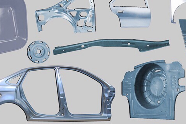
Look around yourself, and you will realize there is an abundance of products made of sheet metal. Be it consumer products such as beverage cans, cookware, file cabinets, or industrial products such as car bodies, frames, and exhausts. Sheet metals are a valuable asset to industries and low volume production. Therefore, this article is dedicated to discussing sheet metal design basics and some helpful tips for sheet metal designers. Many industries are adopting the concept of Design For Manufacturability, or more commonly known as DFM. In sheet metal design industries, DFM helps avoid technical errors in the design process to improve the manufacturing lead times based on the sheet metal thickness chart and preceding calculations. That is why sheet metal design for manufacturability is also an important topic discussed in this article.
What is Sheet Metal?
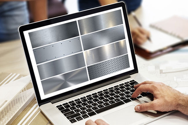
Before discussing the technicalities of sheet metal design, it is essential to understand what sheet metal is. Sheet metal is a metal such as aluminum, brass, titanium, nickel, tin, and copper processed into thin flat pieces like foils, leaves, and plates.
Since they are formed to be light, thin, stable, and elastic, they are extensively used in industries for cladding and covering purposes.
Basic Sheet Metal Operations
Metal sheeting involves forming and cutting operations on metal sheets, coils, and strips to manufacture components and parts of products. There are several different operations for sheet metal designs, some of which are discussed below.
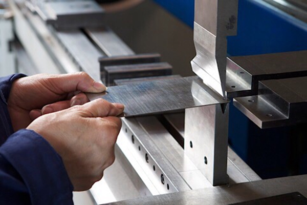
1. Bending
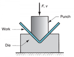
The straining of metal sheets around a straight axis by applying a force at a localized area is called bending. The workpiece is placed over a die block, and a punch is pressed down, forming the desired shape of the metal sheet. Different industries employ different tools to bend metal, but the most common tools are brake press or bending brakes.
2. Drawing
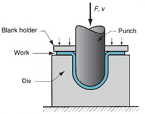
Another metal sheeting operation is drawing, also known as cup drawing or deep drawing. It involves the stretching of sheet metal to form a hollow or concave shape. A blank holder holds the workpiece in a die, meanwhile, a u-shaped punch punches the workpiece of sheet metal. The attached figure illustrates the process:
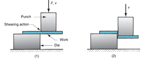
3. Shearing
Unlike the operations discussed above, shearing is a metal sheeting process involving cutting the workpiece by applying force on the punch, rather than a sheet metal design forming process.
As shown in the figure, the metal piece which is first placed on the die experiences a vertical force on the punch to produce a shearing effect and cut the workpiece.
4.Miscellaneous Processes
There are various other processes for sheet metal design that may or may not use the die and punch tools to bend metal. These processes include
- Spinning: The spinning operation comprises the pressing of an axially symmetric metal piece over a rotating chuck or mandrel to shape the metal sheeting.
- Stretch forming: Stretch forming involves stretching sheet metal and bending it simultaneously along with stretching to form contoured shapes.
- Embossing: It creates lettering or raised surfaces on sheet metal.
- Squeezing: It is a combination of processes like sizing and coining to create ductile metals.
- Trimming: Also known as shaving, trimming involves removing burrs the cut edges to make them smooth.
- Piercing: It is a process of creating any shaped holes in sheet metals using a sharp and pointed punch to pierce through the workpiece.
- Punching: Punching creates circular holes on a piece of sheet metal using a punch and die.
- Blanking: It involves cutting a given shape from the sheet metal strip. This cut piece is called a blank. Blanking is commonly used for creating discs or washers.
DFM guidelines for sheet metal design
Variations in computer-aided designs and actual products are unavoidable; however, following the DFM guidelines can reduce these errors. DFM or the Design for Manufacturability is based on the concept of designing parts components, parts, or products so that they are easy to manufacture and are less costly. It focuses on reducing the overall production cost by reducing the lead time.
Research suggests that manufacturers spend around 40% of their time fixing errors, 24% of which are manufacturability errors. Therefore, industries must address these errors. Adhering to the DFM guidelines can significantly reduce design errors.
DFM focuses on simplifying designs of parts for easy manufacturability and reproducibility. It suggests standardization of parts to reduce part count and produce cost-efficient quality products.
Some basic factors for sheet metal design
The Sheet Metal Design for Manufacturability focuses on points that are critical in the overall design process. The following guidelines help improve the design:
- Hole Radius
Creating small holes on the metal piece should be avoided as they require small punches, which may break during the operation. Therefore, holes must have a diameter equal to or more than the workpiece’s thickness.
- Bend relief
An indentation on the sheet designs is called bend relief so that the bending process is smooth during the sheet metal design process. It helps avoid breakage during the bending operation.
- Hole to bend clearance
It is recommended that the distance between holes and a bend be 1.5 times the sheet thickness with the bend radius added to it.
- Sheet metal bend radius
A minimum sheet metal bend radius should be adapted. This minimum bend radius depends on the tools used to bend the metal. The flexible is the metal, the easier it becomes to have a small radius.
- Flange Width
In a sheet metal design, the minimum flange width should ideally be four times the thickness of sheet metal. This factor is vital when it comes to the aesthetics and cleanliness of your design.
DFM tips for sheet metal design
Here are mentioned some sheet metal design tips for manufacturing your design.
1. It is necessary to have greater hole diameters in comparison to the thickness of sheet metal.
2. The distance between two holes matters the most. It is recommended that this distance should be double the thickness of the sheet. This factor will help you prevent the metal deformation of punched holes.
3. If the punched holes are very close to the outer edge of the sheet, it is recommended to have a minimum space equal to the thickness of the sheet between the hole and the edge.
4. There should be at least 1.5 times the material’s thickness space between the bend and the holes.
Benefits of DFM
DFM provides a mart option to manufacturers for improving the quality of their product while reducing the production costs. It has an unending list of benefits, some of which are listed below:
- Highly cost effective
- Decreases labor costs
- Enhances the quality of product
- Improves customer satisfaction
- Reduces the product development time
- Simplifies and standardizes design for easy manufacturability
Mistakes to avoid when designing sheet metal parts
There are certain frequently occurring issues in a sheet metal design. Some of the issues are listed below that must be avoided in the design of the sheet metal part:
1. Avoid the use of 3-D models without any bends
2. Restrain the perfectly perpendicular and sharp corners of sheet metal
3. Prevent the placement of features close to the bend lines
4. Research well before picking a flat pattern for the designed sheet metal parts
5. Avoid selecting the wrong sheet metal fabrication type for the design of a product
6. Must include detailed Specs in the CAD design file depending on the sheet metal thickness chart
7. Keep an eye on the welding requirement, make sure you don’t get them unrealistic
8. Always consider the strength of the U-channel in your material selection process
Sheet metal prototyping
Sheet metal prototyping involves modeling a sample of a metallic product for testing a concept. It helps companies test an idea before launching mass production. Unlike traditional prototyping, sheet metal prototypes are designed in less time.
Different companies employ different methods for sheet metal prototype production, some of which are mentioned below:
- Precision prototype metal stamping uses a stamping press to develop high-precision pieces.
- Rapid prototyping fabricates the model using a 3D virtual drawing.
- Incremental sheet metal forming uses a milling machine to form the product without a die.
Conclusion
Sheet metals have an undeniable significance in our lives. They have vast applications ranging from appliance industries, automotive industries, robotic industries, and consumer products. Therefore, it is essential to understand the basics of sheet metal design and the DFM sheet metal design guidelines considered in the manufacturing process.