Difference Between Tolerance and Allowance in Engineering

tolerance and allowance

Machining is getting more and more precise at a fast pace, with innovative technologies frequently entering the market. Machining allowance and tolerance are two key concepts that engineers use to define the level of machining accuracy they want.

To take full advantage of new improvements in the machining and manufacturing industry, it is important to understand the difference between these two concepts and how they work. In this article, we will present a comparison of allowance vs. tolerance by explaining them separately and highlighting their differences through practical examples.

What is Tolerance in Engineering?

Tolerance is a concept in engineering design that quantifies the unplanned deviations in the dimensions of machined parts. As is common knowledge, even the most precise CNC machine cannot always produce a part with totally exact dimensions. There is always some error as no machine is perfect in the absolute sense.

The goal of engineering and machinists is to use their skills to bring these deviations down to an acceptable range. This range is defined by tolerance, which puts an upper and lower limit on how much the dimension can deviate from its true value.

tolerance in drawing

Importance of Tolerances in Production

The idea of tolerance is highly practical and universal in machining as it provides a reference range of dimensional deviations that machinists can use as a target.

For example, a professional machinist may decide to use a normal machine rather than engaging a precision CNC machine with +/- 0.001 mm accuracy to produce a part with only +/- 1 mm tolerance requirements. This would save cost, resources, and time.

Furthermore, tolerancing also provides a guideline to the quality department on how carefully to verify the dimensions of a part after machining. In quality control, engineers also regularly use advanced tolerancing techniques like tolerance stacking to convey design intent.

What’s important, it is also a necessary provision for the concept of ‘interchangeability’. In machine shops with bulk orders, each part must be similar to a certain tolerance level. The tolerance levels set the base standard for a part to be the same as its other counterparts.

Different Tolerancing Strategies in Engineering Drawings

Now, let us dive deeper into the topic and discuss different tolerancing strategies in engineering drawings with examples.
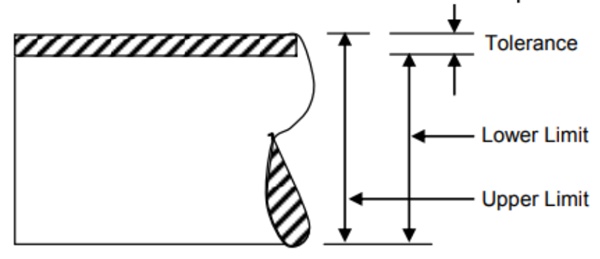
Direct Limits

Direct limits tolerancing mentions just the minimum and maximum allowable size of a dimension. It is one of the popular tolerancing methods in engineering drawings and is preferred due to its clarity and space-saving. However, the base value of the dimension remains unknown, which can be irksome if you need it.

drirect limits in tolerance

In the example, the illustration indicates via direct limit tolerances that that dimension can vary between 26.6 and 26.9.

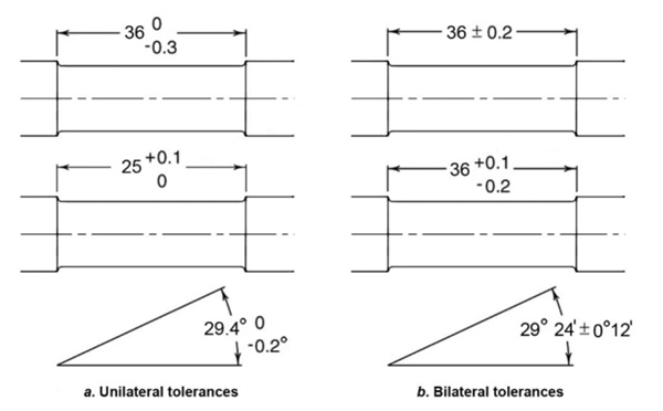
Plus and Minus Tolerances

Plus and minus tolerances are another common tolerancing method in engineering drawings. They define tolerance as a positive and negative deviation (±) from its base value. It is clear and informative, but it takes up a little more space than direct limits, which can make a drawing look a bit messy sometimes.

Within this system, tolerance can be unilateral or bilateral. A unilateral tolerance defines a variation on just one side of the basic size. That is, it is either only positive or only negative. Bilateral tolerance varies on both sides of the basic size, having both positive and negative deviations.

What is Allowance in Engineering?

Allowance is the planned deviation in the dimensions of mating parts to achieve the correct mate. It is a necessary design requirement that allows for functional engineering fits in mechanical assemblies.

The perfect example to explain this is a shaft and hub assembly. To achieve an engineering fit between a shaft and a hub, a specific allowance is defined by the designer between both parts. A positive allowance means there is a small gap between the parts, while a negative allowance represents interference between the mating surfaces.

Allowance and Engineering Fits

The allowance depends on the kind of engineering fit desired. For hub-shaft systems, there are three types of fits: interference fit, clearance fit, and transition fit.

allowance in drawing

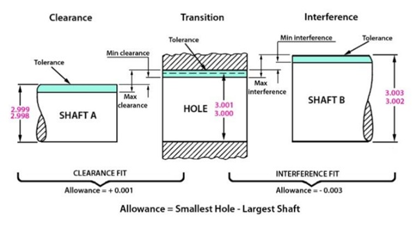
As shown in the figure above, mathematically, allowance is the difference between the smallest hole and the largest shaft. For the clearance fit illustration, the shaft cannot be larger than 2.999 while the hole cannot be smaller than 3.000. Thus, the allowance is +0.001, indicating that it represents a clearance fit.

It is to be noted here that both the shaft and hub have their tolerances as well, as indicated in green. These tolerance ranges are defined on both parts and they work hand in hand in order to get the correct allowance in between both parts after they are assembled.

Importance of Allowance in Production

As we know, The individual part tolerances are chosen based on practical manufacturing constraints. This is the reason that machinists dedicate extra attention and resources to parts with accurate engineering fits, as this translates to a precise allowance and tolerance range as well.

Therefore, allowance and tolerance work hand in hand in mechanical assemblies. The confusion between both terms mainly stems from this.

As mentioned before, allowance is a design feature defining the planned deviation in dimensions of mating components. If both the mating parts are not machined according to the defined allowance, the engineering fit will not function properly.

Allowance vs Tolerance: What are the Differences?

Now, getting back to the allowance vs. tolerance debate, we can take a closer look at how allowance and tolerance differ and why are they so often confused with each other. The following chart summarizes their differences.

AllowanceTolerance
The planned deviation in the dimensions of mating parts.The unplanned deviation in a dimension due to inherent machining errors and imperfection.
Provided only for mating surfaces – also includes specific symbols and terminologies in engineering drawings to indicate the type of fit.Provided on each dimension of a part in an engineering drawing.
Difference between the maximum shaft radius and minimum hole radius (shaft-hub assemblies).Tolerance is the difference between the maximum and minimum allowable dimensions of a part.
Can be positive (clearance) or negative (interference).Specify positive and negative deviations from the base dimension in both directions.

Conclusion

It is common and understandable to mix up allowance and tolerance – they represent similar themes in engineering design. However, it is important to understand their distinction as design engineers and machining experts. Tolerance puts a limit on machining inaccuracy while allowance provides a reference to work against to achieve a specific engineering fit. They are linked, but different.

Your Expert in Machining and Manufacturing: WayKen

WayKen is an industrial expert in rapid manufacturing and prototyping services, including precision machining. Our advanced CNC facility, combined with a highly skilled and experienced team, allows us to meet high-quality production and strict standards.

Whether you require tight tolerances for critical components or need assistance in determining the right allowances for your engineering fit, WayKen is your partner of choice. Contact us with your queries and projects today!

Hi,click here to send us a message.