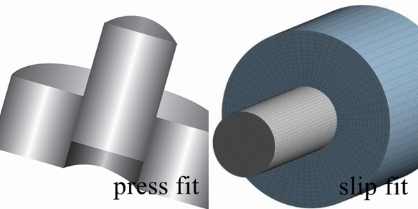
A press fit, also known as interference fit, is a type of engineering fit where the mating components are tightly held against each other through friction. The parts have an intentional interference between the mating surface, which is the cause of this excessive amount of friction.
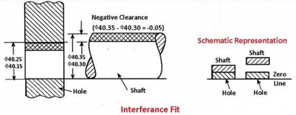
Let us consider the fit of the standard shaft and hub for more clarity. When a hub needs to fit tightly on a shaft to restrict lateral and rotational motions, its hole is intentionally kept slightly smaller than the shaft’s outer diameter. This is called positive interference or negative clearance.
The amount of press fit is communicated to the manufacturing department through engineering drawings, which are then to be maintained by the machinists. A practical example of this is bearing assembly on shafts, where the shaft machining is critical according to press fit dimensions.
Real-life examples of press fit and slip fit design procedures and engineering calculations will be beneficial in differentiating between slip fit vs press fit. After determining that their design requires a press fit, the first decision for an engineer is to choose a suitable tolerance class and basis system depending upon the assembly’s application.
Regarding the basis system, there is either a hole base or a shaft base system. The hole basis system takes the hole size to be the reference (fixed) and suggests the appropriate engineering tolerance range for the shaft. The shaft basis system, on the other hand, is the opposite.
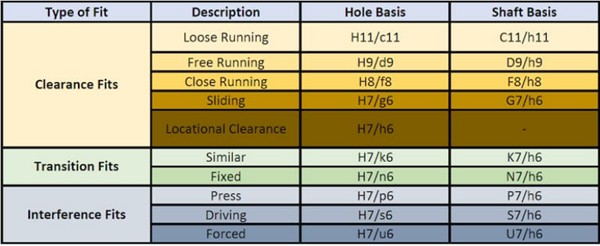
In addition, the tolerance class depends on how tight the fit needs to be. The chart below shows various tolerance classes for different engineering fits, for both the hole and shaft bases.
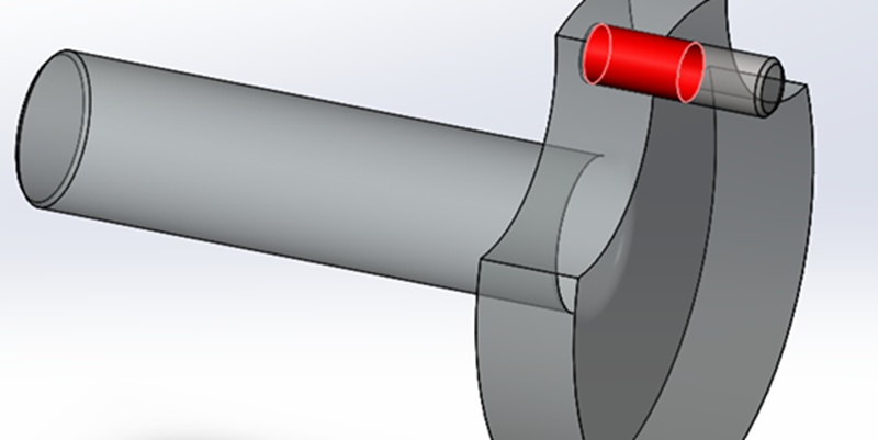
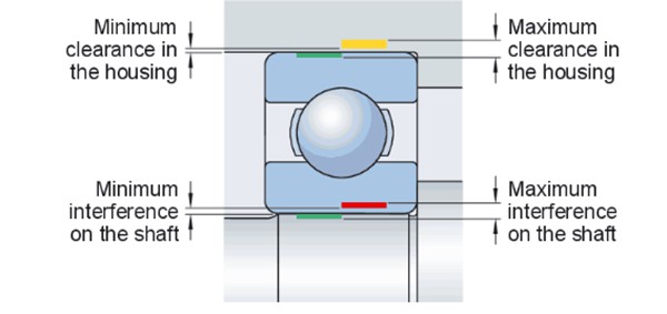
Let us go back to the bearing-shaft example cited before. The figure below shows that the inner ring of the bearing requires an interference fit with the shaft. In this case, since the size of the bearing is standard, the hole basis system is applicable as the size of the shaft is adjustable.
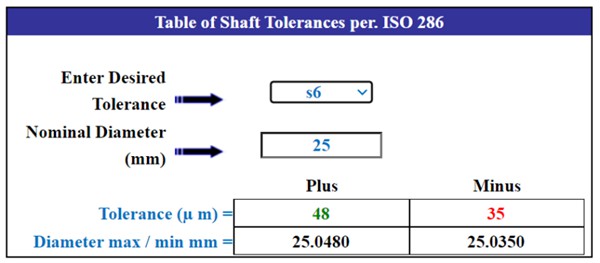
Now, supposing that the engineer opts for a driving type interference fit (H7/u6) and assuming that the bearing’s outer diameter is 25mm, the press fit tolerance on the hole should be +48/-35 μm as per the ISO 286 shaft basis tolerance chart.
We can go one step further and perform engineering calculations to find the force requirements for assembling/disassembling the components. Moreover, we can also find the gripping torque of the final assembly, which is necessary to know in tough loading conditions.
Pressure at the Mating Interface
To calculate the pressure at the mating interface, the following formula applies:
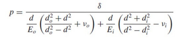
The terms and their respective values for our shaft-bearing case are:
| Symbol | Meaning | Value |
| p | Pressure | 11.98 MPa |
| δ | Radial interference between shaft and hub | +10 μm |
| d | Nominal diameter | 25 mm |
| do | Outer diameter of hub | 27 mm |
| di | Inner diameter of shaft | 0 mm |
| Eo | Young’s modulus of hub | 210 GPa |
| Ei | Young’s modulus of shaft | 210 GPa |
| νo | Poisson’s ratio of hub | 0.25 |
| νi | Poisson’s ratio of shaft | 0.25 |
For simplicity of calculations, we assume that both the bearing outer ring and shaft are made of steel. We also use arbitrary values for some of the other unknown dimensions. Additionally, we assume that the radial interference is 10 μm, which is within the press fit tolerance from the chart.
Plugging all values in the formula gives a pressure of 11.98 MPa. Assuming that the mating interfaces are perfectly smooth (not possible of course), this pressure applies uniformly throughout the mating interface. Thus, this value becomes applicable to the Pmax value we will use in the next calculation.
Axial Holding Force
To calculate the axial holding force (assembling/disassembling force), we can use the formula:

As before, the explanation of the values is in the table below. The contact area is calculated assuming the bearing has a width of 10mm.
| Symbol | Meaning | Value |
| F | Axial holding force | 564.6 N |
| μ | Coefficient of friction | 0.3 |
| Pmax | Maximum pressure | 11.98 MPa |
| w | Bearing width | 10 mm |
| A | Contact area | 157.1 mm2 |
The axial holding force for this setup is 564.6 N. This is the force the fabricator needs to use as a reference while assembling/disassembling the bearing on the shaft. Moreover, the axial loading on the bearing should also not exceed this value to avoid dislocation of the inner ring.
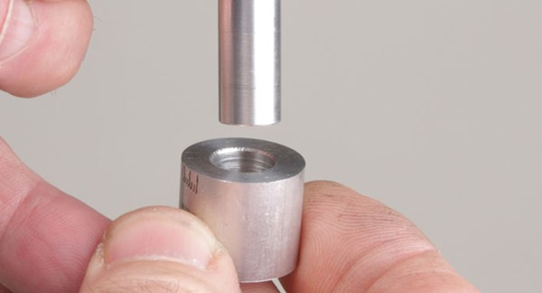
Correctly assembling a press fit is a task that requires skill and attention. Since there is an interference between the mating parts due to the press fit dimensions, their assembly is not as simple as, say, fastening a nut on a bolt.
Generally, there are two popular methods to achieve a press fit.
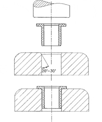
1. Force: The parts are positioned in front of each other, with one part fixed and one mobile. The assembling force calculated in the previous section is applied on the mobile part, which forces it to be pressed onto/into the fixed part, achieving a press fit as a result.
This method relies on raw force and generally requires one of the parts to have a chamfer (typically between 10o-30o at one of its mating corners to ease assembly.
2. Thermal Expansion/Contraction: The other method, more applicable in very tight or precise press fits, is the use of heat. In this method, either the hub is heated to a point that it thermally expands enough to easily slide onto the shaft, or the shaft is cooled to a temperature that it contracts enough to slide into the hub. The latter method is also referred to as shrink-fitting.
Once the assemblage is in position, the components gradually return to room temperature. The resulting thermal expansion/contraction creates the press fit.
Let us move ahead in this slip fit vs press fit comparison. Slip fit assembly components are free to move relatively to each other, unlike press fits where the components are locked. However, the range of motion is still quite restricted. Imagine a door hinge, where the hinge and its pin rotate freely but only within a defined range of motion.
Mechanically, the idea is to leave a small clearance/gap between the mating surfaces so they can easily slip/slide over each other. Another name for clearance is negative interference when defining slip fit tolerance.
Slip fits are relatively easier to evaluate from an engineering perspective. As there is no excessive level of friction due to the lack of elastic deformation at the mating zone, easier to calculate pressure and force.
Slip fit dimensions can be directly picked from a tolerance chart. We can refer to our bearing example from the press fit section. The outer ring of the bearing has a clearance fit with the housing.
In this case, the shaft basis system is applicable as the bearing ring size is constant while the hole in the housing/hub is adjustable.
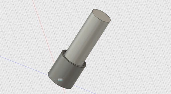
Suppose that the design engineers decided to use a sliding type slip fit (H7/g6) to properly locate the bearing inside the hub while also maintaining ease of motion and assembly. As before, we find the slip fit tolerance from a standard chart.
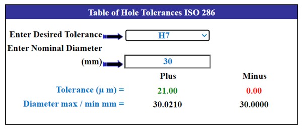
Assuming that the bearing outer ring has a nominal diameter of 30 mm, the ISO 286 standard gives a slip fit tolerance range of +21/-0 μm. While seemingly a very small value, it makes a huge difference in the assembly’s working efficiency and useful life.
Let us round up this entire discussion and boil it down to a few pointers. Slip fit vs press fit differences are not that many but they do create a huge difference in how the assembly works.
Interference/Clearance
The obvious difference between these two engineering fits is that press fit dimensions create an interference between the mating parts and slip fit dimensions create a clearance.
Another way to put it is that in a press fit, the hole is smaller than the shaft, which is why it requires force to assemble them. For slip fits, the hole is larger than the shaft and easily slides over it.
Degrees of Freedom
Another important difference between the two is in the degrees of freedom in motion of the mating components. In a press fit, the mating parts rigidly lock with each other, preventing any sort of motion in any direction.
For slip fits, on the other hand, there is relative motion between the components. For example, in a piston-cylinder system, the piston freely moves along the cylinder’s axis. However, the slip fit still restricts the other two lateral motions.
Mechanical Deformation
Mechanical deformation is another point of difference in the slip fit vs press fit comparison. Generally, the mating parts in a press fit undergo physical deformation at the mating surfaces. In most cases, it is elastic deformation, but plastic deformation can also occur for very tight fits or with plastic materials with poor creep resistance.
On the contrary, slip fit components do not deform due to the positive clearance in slip fit tolerance. There may be some surface wear and tear over time due to sliding action, but that is about it.
Assembly & Disassembly
Assembly and disassembly of press fits are more challenging due to the requirement of force and thermal expansion/contraction.
The fabricators have a lot more parameters to control such as the temperatures, application points of heating/cooling, force, and impact tolerance of the materials. Moreover, there is also a chance of damaging the assembly components during the process. For example, high or misdirected force can sometimes damage bearings during assembly.
On the other hand, slip fits are easier to assemble. Usually, assembly by hand is possible, which is quick, easy, and less risky.
Manufacturability
Press fits may require more precision manufacturing to achieve the necessary interference. As we saw in the calculations section, press fit tolerance is critical for a successful press fit. Small changes in the press fit dimensions can lead to unsustainable pressure levels and subsequent failures.
Slip fits provide more flexibility in manufacturing tolerances, making them somewhat easier to achieve without requiring extremely tight tolerances. Manufacturing accuracy, however, is still a core requirement. The entire interface must be at the correct tolerance level to enable smooth sliding motion, otherwise, the parts can become locked, misaligned, and too loose.
Applications
Different applications are a main point in the slip fit vs press fit discussion. As expected, both have vastly different applications.
Press fits are useful for rigid and permanent connections with minimal or no relative motion between the parts. Examples include bearings, bushings, and certain structural components.
Slip fits are preferable when designers require ease of assembly and disassembly or some degree of movement between the parts. Slip fit applications include housings, hinges, pivots, and piston cylinder systems.