What is Flatness in GD&T?
Flatness in GD&T is one of the many engineering tolerancing tools at the disposal of design engineers to control the size and form of their designs. The flatness tolerance is applicable on surfaces whose flatness must be kept within certain bounds for proper part functionality. It is a common way of controlling the form of a surface where flatness is a design requirement.
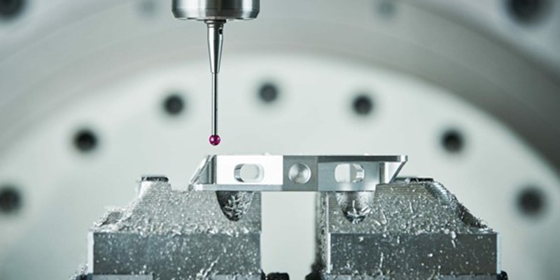
For example, the jaws of a mechanical vice are ground to a highly precise level of flat so that they can grip parts with adequate strength and apply uniform force on the gripped surfaces. In case they are not flat, the grip can be loose and damage the part by inducing stress concentrations.
Flatness Callout and Symbol
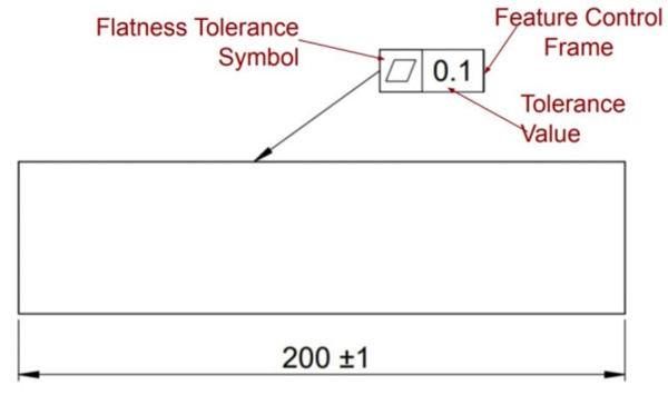
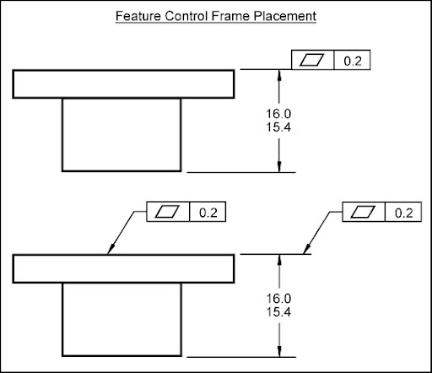
Flatness in GD&T has a specific flatness callout to specify tolerance details on a part. In this section, we briefly explain the feature control for the flatness symbol. A typical flatness callout is shown in the figure below, indicating the position of the symbol and tolerance value in the feature control frame.
The flatness symbol does not require a datum, as we will explain in the upcoming section. As a result, the callout only contains the flatness symbol and tolerance value.
Flatness Tolerance Zone
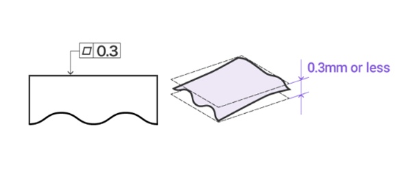
Flatness in GD&T has a 3D tolerance zone that is defined by two parallel surfaces above and below the referenced surface. The entire surface must lie within these two virtual planes for it to conform to the defined quality requirement.
The distance between these planes defines the ‘tightness’ of the flatness tolerance. Based on design intent, the designer sets a tolerance value according to the level of precision required, defining how much room the surface has to deviate from its true form.
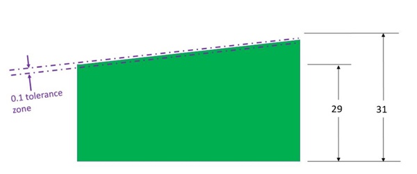
As said above, the flatness symbol does not require a datum as it does not control the referenced feature against a standard datum feature. That is, it enforces an independent form of tolerance on the surface regardless of its position or orientation with respect to other features in the part.
For example, in the figure below flatness is called out on the top surface of the part. All that matters is how flat the top surface is within its 0.1-thick tolerance zone. It does not matter whether it is tilted with respect to the bottom surface of the part.
How to Apply Flatness in GD&T?
There are a few different ways to apply flatness in GD&T, with subtle differences between each. Although flatness is an easy GD&T tool to use, knowing its various applications can come in handy when designing parts with varying geometries and quality requirements.
Flatness on a Surface
This is the most common application of the flatness symbol. It is the same as we discussed above. The surface flatness tolerance zone comprises two parallel planes above and below the surface.
In this case, the flatness callout points directly towards a flat surface or sits on an extension line from the referenced surface.
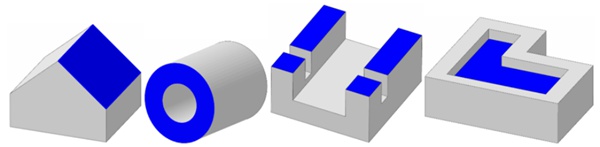
There is no restriction on the placement of the flat surface for the flatness symbol to be applicable. The referenced surface may be inclined, inside a slot, or even discontinuous, as shown in the figure below.
Flatness on a Derived Median Plane (DMP)
Flatness on a DMP is another way of using flatness in GD&T. In this case, the flatness symbol is applied to a feature of size rather than a surface. The control feature is the virtual DMP of the referenced feature of size. This has many practical applications, most notably in stacked components.
Another point to bear in mind when using the flatness symbol on a DMP is that the Maximum Material Condition (MMC) and Least Material Condition (LMC) modifiers are also applicable to it. The flatness callout in the figure below contains the MMC modifier symbol (Ⓜ).
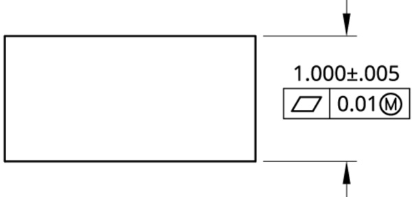
In the example above, the thickness of the part must be within the range of 0.995-1.005 at all points, as per the tolerance. However, due to the flatness callout with the MMC modifier, the overall form of the part (bending, waviness in the DMP) can still vary up to 0.01.
Therefore, the actual functional tolerance zone (Virtual Boundary Condition in GD&T jargon) is 0.005+0.01 = 0.015. It caters to both size and form deviations.
Local Flatness per Unit
The local flatness tolerance is sometimes defined separately on the drawing when the local flatness requirements differ from the overall surface flatness requirement. This happens in cases where the referenced surface is too big and difficult to control, or when local flatness is a functional requirement.
For example, sealing devices like gaskets need not be fully flat as a whole but they must still be very flat in small local zones to provide effective sealing.
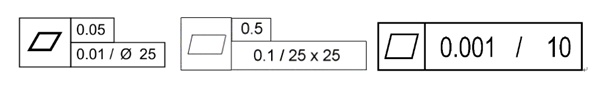
The local flatness can be defined per unit length or area on the surface. A few examples are shown below. The surface must lie within the local tolerance limits for all possible local zones. For instance, in the case where there is 0.01 flatness tolerance per ⌀25, there should be no local ⌀25 circular zones on the surface where it violates the 0.01 tolerance.
How to Measure Flatness with Different Methods?
The next question to answer is how to measure flatness. Once the part is manufactured, it arrives in the quality department along with its engineering drawing, where a quality control professional then evaluates whether the flatness tolerance is met or not.
There are numerous ways to measure flatness with varying degrees of accuracy. We will discuss the main methods in this section and offer a comparison in terms of accuracy, effort, and time.
Height Gauge
A common method to evaluate flatness in GD&T is through a height gauge. The operator places the bottom surface of the part on three columns of equal height. The operator then adjusts the heights of these columns to simulate a perfectly flat plane.
Then, the indicator of the height gauge is slid across the surface and its deviation is monitored throughout the process. If the needle deviation remains within the flatness tolerance, the part passes quality.
This is the standard method for measuring flatness and is generally accurate for general engineering purposes. However, the operator needs to be careful of certain things. Firstly, the flatness of the three-point mounting must be guaranteed. Otherwise, the measurement would be inaccurate due to the consequent tilt in the referenced surface.
Moreover, since the part sits on three columns, some parts of it hang in the air, like a bridge. Due to this, sensitive geometries like thin sheets might bend under gravity or the action of the height gauge. Again, this would lead to a wrong measurement.
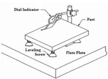
Surface Plate
This method is like the one above, but the part sits on a surface plate instead. The surface plate is most often a flat granite table as it offers good thermal stability and damping.
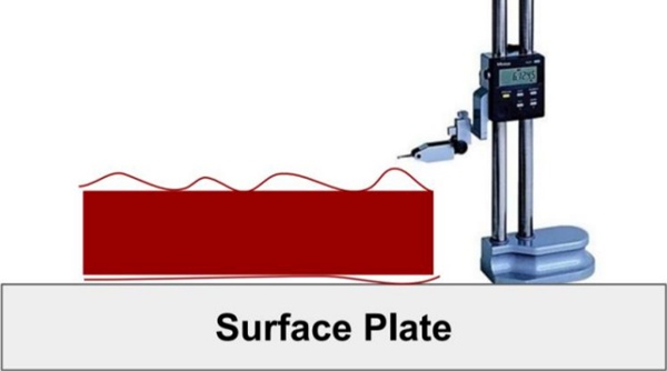
Once securely placed, a dial gauge is similarly slid across the surface and its deviation is monitored.
There is a potential problem in this scenario as well that quality professionals must take care of. The surface plate itself should be flat and properly oriented. If the plate is inclined, the height gauge would instead measure the parallelism between the plate’s bottom end and the referenced surface, which is not what the flatness tolerance specifies.
Therefore, the surface plate should be remarkably flat and horizontal to ensure a precise measurement.
Coordinate Measuring Machine (CMM)
CMMs are the most accurate equipment for measuring flatness in GD&T. They are automated, precise, and independent of plane orientation, unlike the previous two methods. Moreover, CMMs are compatible with CAD software, giving engineers more flexibility and convenience when performing quality checks.
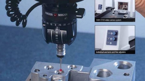
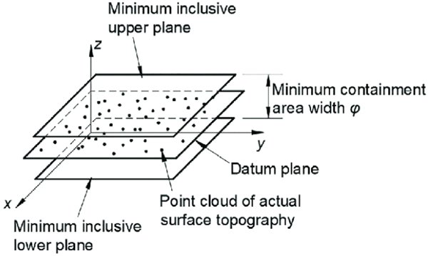
A CMM works by sampling the surface at several points and generating a 3D point cloud. The number of measurements depends on the size of the part and the level of accuracy required. Then, the CMM software evaluates the point cloud to verify the flatness tolerance. The software may use several algorithms to perform this calculation. The two common methods are the best-fit plane and minimum zone algorithms.
For the best-fit plane, the algorithm fits the best possible plane to the collected Cartesian points and then computes this plane’s maximum deviation from extreme points on both sides. This value serves as the flatness tolerance value.
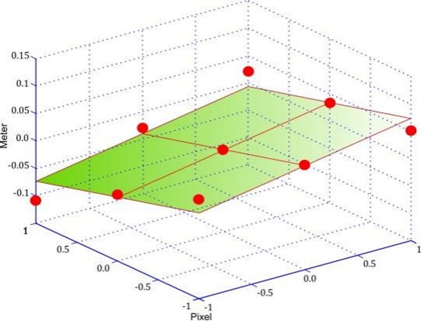
In the minimum zone method, the algorithm fits two parallel, closest possible planes to the entire point cloud. These planes define the tolerance zone and the distance between them is the flatness of the surface.
Differences Between Flatness vs. Straightness
There is a common confusion between the straightness and flatness symbols in GD&T. Their applications are quite similar; therefore, confusion is natural. Essentially, flatness in GD&T is the 3D version of straightness.
In this section, we will present a comparison of straightness vs tolerance, so design engineers are clearer about these concepts while designing products.
| Flatness | Straightness |
| Flatness controls a 2D plane. | Straightness controls a 1D line. |
| The flatness tolerance zone is the 3D space between two parallel planes. | The tolerance zone is the 3D space within a cylinder around the referenced line. |
| Applies on a planar surface or DMP. | Applies on a straight line or axis, which is not necessarily on planar surfaces. |
| Applications generally focus on maintaining adequate contact between mating surfaces. | Applications of straightness include the alignment of linear features and axes. |
WayKen Ensure GD&T for Your Machining Projects
(GD&T) ensures precise and accurate manufacturing processes for all machining projects, It allows for clear communication of design requirements, ensuring that parts are produced to exact specifications. With WayKen’s expertise, our customers can rely on consistent quality due to insisting on strict GD&T standards, minimizing errors, and maximizing efficiency. Whether custom CNC machining, 3D printing, or rapid injection molding, WayKen’s commitment to GD&T guarantees that every component meets the strict standards of precision and functionality.