What is Straightness in GD&T?
Let us briefly introduce what is straightness general before we take a deep dive into the specifics. As the name shows, it is a GD&T symbol that controls the straightness of a geometric entity. The nature of the entity can vary, as we will shortly see, but the basic concept remains unchanged.
In engineering design, straightness tolerance can be applied in several ways. A table, for example, needs to be straight enough (or flat, you will understand the technical difference soon) that objects remain stable on it and do not roll off.
Another example can be the inner ring of a bearing. Its surface needs to be very straight along the axial direction so that it fits well on a shaft. A lack of straightness in this case can misalign and damage the bearing.
Straightness Callout and Symbol
GD&T has a very standard way of defining tolerances on an engineering drawing. In this section, we will introduce the straightness symbol and its callout in an engineering drawing.
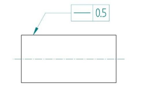
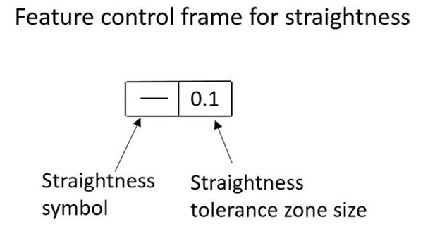
The straightness symbol is just a flat, horizontal line – like a dash. The callout is referenced either on a surface or a feature of size. The figure below shows a very simple example.
It is important to note that straightness in GD&T is not relative to a datum, which is a requirement for other symbols like parallelism.
Now, let us distinguish between the two main ways to use straightness in GD&T: surface straightness and straightness tolerance on a derived median line.
Surface Straightness in GD&T
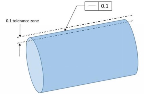
A common application of surface straightness is on flat or cylindrical surfaces. It establishes a tolerance zone for upper and lower deviations along a 2D line on the surface. For flat surfaces, the 2D line can be anywhere on the surface, and for cylindrical surfaces, the 2D line is parallel to the axis.
This surface straightness in GD&T is not called on features of size, but rather the reference surface directly.
How to Measure Surface Straightness?
Engineering verifying the surface straightness tolerance requires precision equipment and skill from quality personnel. There are two main methods to perform surface straightness measurements.
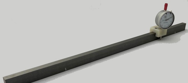
Dial Gauge
Dial gauges, or height gauges, are the standard equipment for manual straightness measurement. The dial’s contact point is placed against the surface after properly securing the gauge and then slid across the desired 2D line of measurement.
It is important to ensure that the dial is calibrated, set to zero, and the plunger is slightly pressed in before the measurement begins. Following these standard operating procedures guarantees precision measurement.
If the variation of the dial along the entire measurement length is within the defined tolerance limits, the part passes quality control.
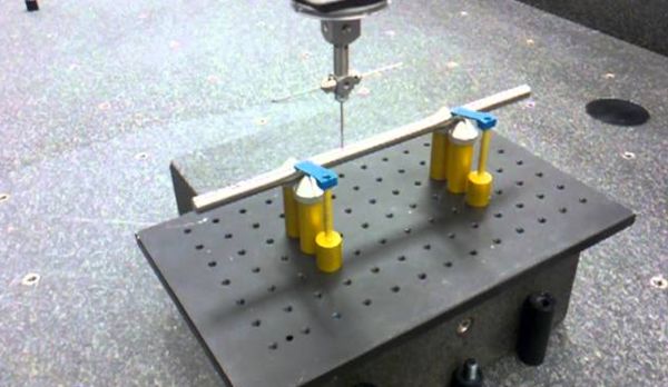
Coordinate Measuring Machine (CMM)
The other method to perform straightness measurement is using a CMM. This method gives more precise results than dial gauges. It is an automatic method that requires CMM programming.
After mounting the part on the CMM’s bed, the measurement probe samples the surface along the reference measurement line and produces an automated report for the operator showing whether the part is in tolerance or not.
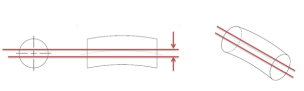
Straightness on Derived Median Line in GD&T
The derived medial line (DML) is the imaginary axis of a part with axisymmetric features. Typically, this applies to cylindrical shapes. Applying the straightness tolerance on a DML controls its straightness by establishing a perfect cylindrical tolerance zone around it.
Moreover, note that in this case, the tolerance zone is a 3D cylinder around the true axis of the feature. It is useful in catching twists, bends, and other geometric irregularities in the part’s form.
Furthermore, this application of the straightness symbol also does not need a datum. In GD&T, several symbols require the definition of datum features to be used as a reference for measurement. For example, the perpendicularity symbol. For an edge to be perpendicular to something, a datum is required to measure perpendicularity. The straightness symbol does not require a datum.
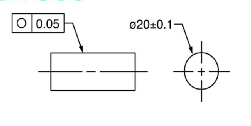
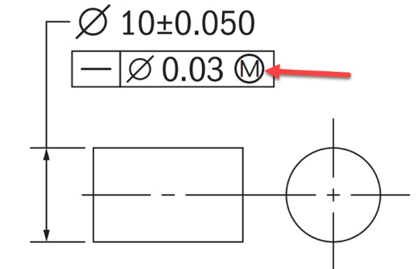
MMC/LMC Callout
There is a special case for straightness in GD&T in DML cases, where engineers use the maximum material condition (Ⓜ) modifier along with the straightness symbol.
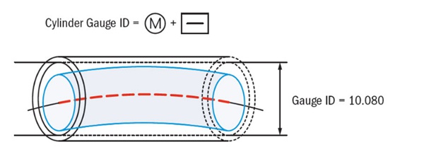
The MMC(maximum material condition) modifier is a functionality-based callout that focuses on ensuring that the part does not interfere with its mating components, even in its worst condition. That is when it has the maximum material due to inaccuracies.
In the case of shafts, the MMC occurs when the shaft is at its maximum possible size. At this size (MMC), the entire shaft must fit inside a hole having an equivalent diameter to the MMC. The formula linking the three concepts of MMC, straightness tolerance, and gauge hole size is:

Suppose we have the following case of straightness in GD&T with the MMC callout.
Applying the formula along with the reference values from the GD&T callout gives us a cylinder gauge size of 10.08. This represents the maximum allowable deviation in the part, which consists of 0.05 from the size tolerance and an additional 0.03 from the straightness.
Bonus Tolerance
Furthermore, at this point, it is important to introduce the concept of bonus tolerance. This applies when the part size is not in its worst condition. That is, its diameter is less than 10.05, which is the allowed maximum. In this case, the straightness tolerance can increase by the amount the diameter is less than its maximum value, which is 10.05.
Hence, for instance, if the shaft size is 10.03, the bonus tolerance will be 0.02 (10.05 – 10.03). Therefore, this will be added to the straightness tolerance, which will now become 0.05 (0.03 + 0.02).
This is an advanced concept that requires a deeper understanding of MMC/LMC and GD&T in general. However, this simple example shows how straightness in GD&T behaves when used for controlling a DML along with the MMC callout.
How to Measure the Straightness of a Derived Median Line?
Straightness measurement for derived median line features is slightly different from our previous case. The most popular method to perform this measurement is using a cylindrical gauge, where a hole acts as a quality-checking device.
If the part easily fits inside the hole with minimal interference at any point, the part passes quality.
Moreover, engineers can also choose to use a CMM. This works by sampling the part’s center at different positions along the axial direction. However, this method is time-consuming and only useful in a handful of cases. Mostly, checking if the part is functional using a cylindrical gauge is a good guarantee of its quality.
Straightness vs. Flatness: What’re the Differences?
Flatness is a very similar concept to straightness in GD&T, leading to frequent confusion for designers, production engineers, and operators. This section will break down the differences between these two and present an easy-to-understand comparison of straightness vs flatness.
- Line vs. Plane: In the simplest of words, flatness applies on an entire surface while straightness in GD&T controls only a line.
- 2D vs. 3D: Another way of looking at the straightness vs flatness comparison is that flatness controls a 3D object while straightness is 2D.
- Control Features: The flatness symbol is restricted to flat surfaces, the entirety of which must lie within the tolerance zone. Straightness, on the other hand, gives designers more choice as it applies to lines, edges, axes, and centerlines.
Conclusion
Straightness in GD&T is an important component in an engineering toolkit. It offers engineers the ability to convey design intent and tolerance requirements to manufacturers and applies to several geometric features.
Handle Your Engineering Projects with WayKen
WayKen has an engineering team with expertise in varying manufacturing processes. We provide test parts similar to end-use products using custom CNC machining, rapid tooling, and injection molding techniques. In addition, we assist you in checking engineering drawings to ensure compliance with predetermined production requirements before prototyping or manufacturing. Get a free quote today to start your new engineering projects!