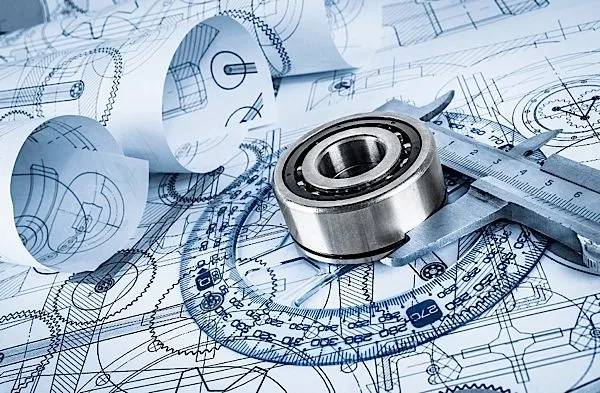
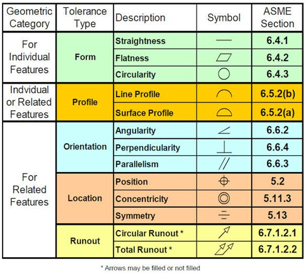
GD&T is a feature-based system for defining the size, shape, and location of features on parts. Geometric tolerances are applied to features by feature control frames. The commonly used tolerance categories are form, profile, orientation, location, and runout.
The GD&T symbols are neatly grouped into many groups according to their intended function.
Form tolerances control
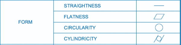
Form controls define the overall shape of a feature, including straightness, flatness, circularity, and cylindricity
Straightness
It also known as straightness degree, refers to the actual linear geometry of a component that preserves an ideal straight line. Straightness tolerance refers to the maximum deviation of the real line from the ideal straight line.
Flatness
Flatness, also known as flatness degree, refers to the actual planar form of a component that preserves an ideal plane. Flatness tolerance refers to the greatest deviation of the real surface from the ideal plane.
Circularity
Circularity is often referred to as the degree of roundness. It is the real circular shape of a component that maintains a consistent distance from its center. The greatest permissible variance between the real and ideal circle in the same cross-section is called the roundness tolerance.
Cylindricity
Cylindricity refers to every point on the cylindrical surface of the component being maintained equidistant from its central axis. The cylindricity tolerance is the greatest deviation permitted between the real and ideal cylinders.
Profile tolerances control
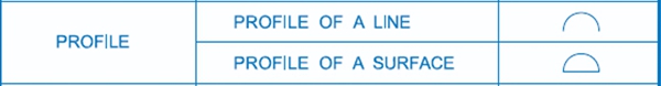
Profile control describes the three-dimensional tolerance zone around a surface. It includes the profile of a line and the profile of a surface.
Profile of a line
The line profile of a part in the state of a curve of any form in a specified plane that maintains its ideal shape. The tolerance for line profiles refers to the amount of variance that may occur in the actual contour of an irregular circular curve.
Profile of a surface
The profile of a surface is the condition that indicates the surface of any shape on the part, maintaining its ideal shape. It is the actual contour line of the non-circular surface and the amount of variation allowed for the ideal contour surface.
Orientation tolerances control
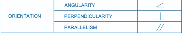
Orientation control defines the position of features and is concerned with dimensions that vary at angles, including angularity, perpendicularity, and parallelism.
Angularity
The inclination property states that the relative orientation of two elements on a part is kept at the specified angular dimension. The tilt specified tolerance for the maximum deviation allowed between the actual orientation of the element being tested and the ideal orientation at any specified angle to the datum.
Perpendicularity
Perpendicularity of the degree of orthogonality, between two elements indicates that the measuring element on a component maintains a proper angle of 90° with respect to the reference element. The perpendicularity tolerance is the difference between the actual direction of the measuring element and the maximum permissible variance between the predicted orthogonal directions to the reference phase.
Parallelism
Parallelism, often referred to as parallelism degree, is the distance at which the actual elements on a part remain equal to the datum plane. The maximum allowable variation between the actually measured element direction and the expected direction of parallel planes to the datum is parallelism tolerance.
Location tolerances control
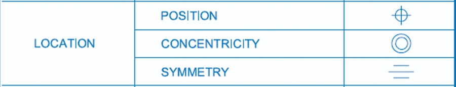
Location controls are used to establish the location of a feature using linear dimensions, including position, concentricity, and symmetry.
Position
The degree of position refers to the precision with which a point, line, surface, or other feature on a part is located in relation to its predicted location. Location tolerances refer to the greatest variance in the actual position of the measured element compared to the ideal position.
Concentricity
Sometimes abbreviated as coaxial degree, refers to the fact that the measured axes on a component stay parallel to a reference axis. Coaxial tolerance refers to the permissible deviation of the actual measurement axis from the datum.
Symmetry
Symmetry refers to the condition of a part in which two symmetrical center components stay in the same center plane (or centerline, axis). The permissible deviation of the ideal symmetry plane’s real symmetry center plane is referred to as symmetry tolerance.
Runout tolerances control
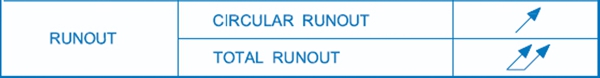
Runout controls define how much a particular feature can vary in relation to the datums. It includes circular runout and total runout.
Circular runout
The term “circle beat” refers to a condition in which the rotating surface of a part is contained inside a designated measuring plane and maintains a constant position relative to the datum axis. Within a certain measurement range, the maximum permitted variance is the circular beat tolerance when the actual component being measured is spun completely around the datum axis without axial movement.
Total runout
When a component rotates continuously around the datum axis, full run-out refers to the quantity of run-out as well as the complete measured surface. Full beat tolerance is the highest permitted beat when the actual element under test is rotated continuously about the datum axis and the indicator travels generally along its predicted contour.
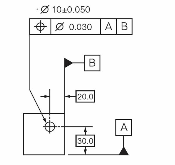
What is a feature control frame? In geometric design and technology, a feature control frame is used to explain the requirements and tolerances of a geometric control applied to a part’s feature. The feature control frame is made up of four major pieces of information, including:
GD&T sign, also known as a control symbol
The shape and size of the tolerance zone
Various tolerance zone modifiers are available, such as material condition modifiers and projections
Datum references
This information provides everything you need to know how the geometrical tolerance should be understood, as well as how to measure or decide whether the component is within specification.
Parts of the feature control frames
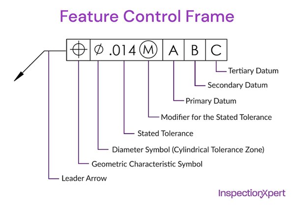
Parts of a feature control frame include the leader arrow, geometric symbols, tolerance zone, etc.
- Leader Arrow
This arrow directs attention to the feature on which the geometric control is located. (As indicated, the extension line may be used or not used.)
- Geometric Symbol
This is where you will provide the geometric control that you want to use.
- Diameter Symbol
If the geometric control is a diametrical tolerance, this symbol (Ø) will appear in front of the tolerance value before the tolerance value.
- Stated or Tolerance Value
The tolerance zone specifies the geometric control’s total tolerance. The drawing standard serves as the basis for the unit of measurement and basic dimension.
- Size or Tolerance Modifiers
This is where you identify any features that may require special tolerance consideration. For example, a feature with tight tolerances may require a larger datum target than one with looser tolerances.
- Datum Feature Reference (Primary Datum Features Reference)
The major datum feature utilized for the GD&T control is this one if a datum is needed for the control. The letter relates to a feature on the part that will be marked with the same letter when the part is completed. When measuring the component, this is the datum that must be limited first in order to be accurate. It is vital to note that the sequence of the datum is critical for the measurement of the component.
- Secondary Datum References frame
The secondary datum references will be cited to the right of the main datum reference frame if one is necessitated. This letter refers to a feature on the part that will be marked with the same letter in the same location on the part. This is the datum that is fixed after the main datum during the measurement process.
- Tertiary Datum Features Reference
The third datum will be linked to the right of the secondary datum feature reference if it is necessary. This letter refers to a feature on the part that will be marked with the same letter in the same location on the part. During the measuring process, this is the datum that is fixed last.
GD&T has the advantage of describing the design intent rather than the actual geometry. Similar to a formula or a vector, it is only a representation of the item.
In order to decrease assembly failures and the means required for quality control, statistical process control (SPC) may be utilized with GD&T. This is a huge money-saver for businesses. Since GD&T, many departments may collaborate on the same project because they all speak the same language and have the same goal in mind. So, GD&T is used in a wide variety of situations in production and manufacturing.
GD&T in Drawing
The engineering drawing serves as a check and balance to verify that the vendor is producing exactly what the customer’s design calls for. +/-.002 is a very tight tolerance when it comes to precision “it becomes even more critical to use GD&T. Cylindrical to the nearest.0003 is required for cylinders that need to be “cylindrical.” “In this case, for example, you can get up and running with it quite fast.
GD&T in CNC machining
One of the benefits of CNC machining is the ability to produce parts with very tight tolerances. This is possible because the cutting tools are controlled by a computer, which allows for very precise movements. In order to take full advantage of this capability, it is important to use proper GD&T.
In CNC machining, GD&T is used to specify the tolerances for each dimension of the part. This ensures that the finished part will meet the requirements of the design. GD&T is also used to specify the location of features on the part, such as holes and slots. This helps to ensure that the features are machined in the correct location and that they are aligned correctly.
Although not every CNC machined part requires the technical skill of GD&T, when advanced CNC machining is required, GD&T is a good method to utilize. Consider the following 5 advantages of GD&T use in CNC machining:
- Simple communication
GD&T enables you to transmit a great deal of information about the design of your component using a limited number of characters, numbers, and symbols. There is no need for lengthy explanations! The ability to communicate effectively decreases the amount of time spent back and forth between you and the contract manufacturing service provider.
- Precise production
Due to the precision with which GD&T is articulated, ambiguity in the description of a CNC part’s design is minimized. As a consequence, you can be certain that your product will be made precisely and will perform as intended in the field.
- Known tolerances
GD&T provides producers with a comprehensive grasp of the tolerances associated with a particular item. It offers the highest tolerance necessary for the CNC component to work correctly, which simplifies the part and prevents you from wasting on a minimal tolerance that you may not need.
- Universal language
You may find yourself in a position where you want to deal with a contract machining firm located in a nation where the native language is not English. Fantastic news! GD&T is a globally recognized universal language, removing irritating language hurdles for international manufacturing.
- Proper assembly
If you have two mating CNC components that must interface in an assembly, GD&T is a good method of communicating how this interface should be accomplished. In these instances, GD&T clearly displays the tolerances associated with each item, allowing producers to quickly determine whether a measurement is incorrect and modify it appropriately.
GD&T in 3D printing
The use of GD&T in 3D printing is becoming increasingly popular as the technology continues to evolve. This is due to the fact that it provides a more accurate representation of the finished product, which can be extremely helpful when manufacturing complex parts.
In order for GD&T to be effective, it must be used in conjunction with accurate measurements. 3D printing is an additive process, which means that the final product is built up layer by layer. As such, it is important to take into account the fact that each layer will be slightly different from the one below it. This can lead to inaccuracies in the final product if GD&T is not used correctly.
Numerous product designers and engineers utilize 3D printing for quick prototyping and rapid tooling throughout the product development process to create cost-effective prototypes and unique components that would otherwise need considerable tooling expenditure.
Tolerancing in 3D printing is distinct from tolerances in typical manufacturing equipment since 3D printing is a single automated operation. While tighter tolerances demand more work during the design phase, they may result in considerable time and cost savings throughout prototyping and production.